
SLX V6-3.2L SOHC (1996)
Information Bus: Description and Operation
Class 2 Serial Data Bus
CLASS 2 SERIAL DATA BUS
OBD II technology requires a much more sophisticated PCM than does OBD I technology. The OBD II PCM diagnostic management system not
only monitors systems and components that can impact emissions, but they also run active tests on these systems and components. The decision-
making functions of OBD II PCM have also greatly increased. To accommodate this expansion in diagnostic complexity, Isuzu engineers have
designed the Class 2 serial data bus, which meets SAE J185O recommended practice for serial data.
"Serial Data" refers to information which is transferred in a linear fashion - over a single line, one bit at a time. A "Data Bus" is an electronic
pathway through which serial data travels.
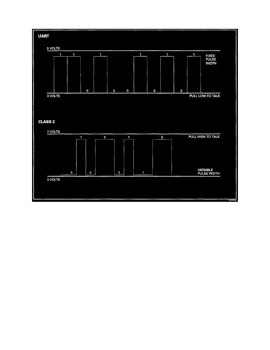
TROOPER previously used a 5 volt data bus called UART, which is an acronym for "Universal Asynchronous Receive and Transmit". When
neither the vehicle's control module nor the diagnostic tool, such as a TECH1, are "talking," the voltage level of the bus at rest is 5 volts. The two
computers talk to each other at a rate of 8,192 bits per second, by toggling or switching the voltage on the data bus from 5 volts to ground.
Class 2 data, which is used on OBD II vehicles, is quite different. Data is transferred at a rate of 10.4 kilobits per second, and the voltage is
toggled between zero and 7 volts. The rest voltage on Class 2 data systems is zero, or ground, and is switched activate at 7 volts.
Class 2 data is also pulse width modulated. Each bit of information can have one of two lengths: long or short. On the other hand, UART data bits
come in only one length (short). The pulse width modulation of Class 2 data allows better utilization of the data line.
The message carried on Class 2 data streams are also prioritized. This means that if two devices try to communication on the data line at the same
time, only the higher priority message will continue. The device with the lower priority message must wait.
NOTE:
The Class 2 data wire is always terminal 2 of the new 16-Terminal Data Link Connector (DLC).