
TL L5-2451cc 2.5L SOHC MFI (1997)
Audible Warning Device: Diagram Information and Instructions
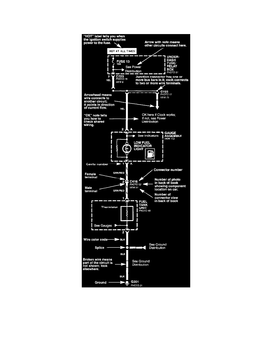
How to Read and Use the Circuit Schematics
Schematic Layout
Circuit Schematics
Each schematic represents one circuit. A circuit's wires and components are arranged to show current flow, from power at the top of the image, to
ground, at the bottom.
Connectors
All in-line, pigtail, and fuse box connectors are numbered (C725, C416 etc). Component connectors are not numbered but are identified by the
name of the component. If a component has more than one connector, each connector is assigned a letter (A,B,C etc). Below most connector
numbers and component names are PHOTO and VIEW numbers. The PHOTO number refers to a photo that shows the connector's location on the