
TL L5-2451cc 2.5L SOHC MFI (1997)
Lock-Up Control Solenoid Valve: Testing and Inspection
NOTE: Lock-up control solenoid valves A and B must be removed/replaced as an assembly.
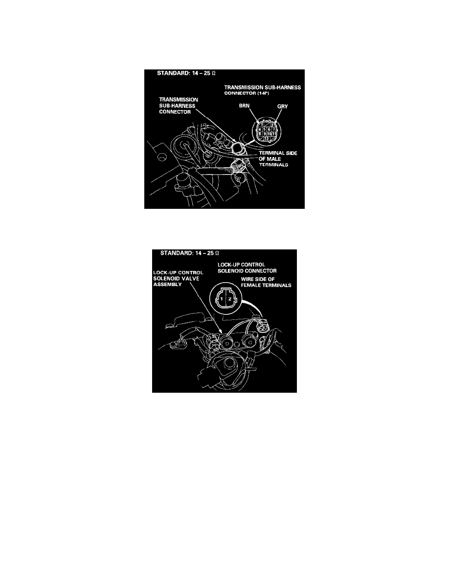
1. Disconnect the transmission sub-harness connector (14P).
2. Measure the resistance between the No. 1 terminal (solenoid valve A) of the transmission sub-harness connector and body ground, and between the
No. 3 terminal (solenoid valve B) and body ground.
3. If the resistance is out of specification, disconnect the 2P connector from the lock-up control solenoid valve A/B.
4. Measure the resistance between the No. 1 terminal (solenoid valve A) of the lock-up control solenoid connector and body ground, and between the
No. 2 terminal (solenoid valve B) and body ground.
5. If the resistance is OK, replace the transmission sub-harness.
6. Replace the lock-up control solenoid valve assembly if the resistance is out of specification.
7. If the resistance is within the standard, connect the No. 1 terminal of the lock-up control solenoid valve connector to the battery positive terminal.
A clicking sound should be heard. Connect the No. 2 terminal to the battery positive terminal. A clicking sound should be heard. Replace the
lock-up control solenoid valve assembly if no clicking sound is heard.