
TL V6-3.2L (2004)
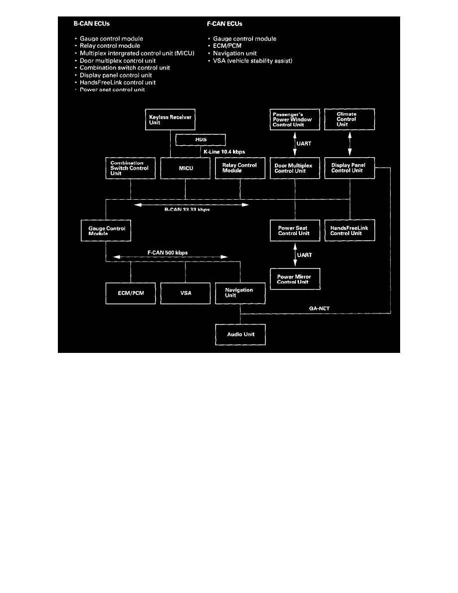
Connected ECUs
Several ECUs are connected to each of the two networks. The gauge control module is part of both networks since it is the "gateway" between them.
Here is a list of ECUs and the network they are connected to.
Network "Loss of Communication" Error Checking
The B-CAN and the F-CAN send messages to each other to check the integrity of the network communication circuit. They do this by sending a specific
digital message out after an event. For example, after turning the ignition switch to ON (II). After the switch to ON, all the ECUs on the communication
circuit expect to receive a message from other specific units within a specified amount of time. If the message is not received, the ECU will transmit a
DTC reporting that the control units did not communicate.
Examples of communication circuit test
Normal circuit
1. Ignition switch is turned ON (II).
2. The door multiplex control unit transmits a door switch signal.
3. The multiplex integrated control unit (MICU), relay control module, and gauge control module receive the door lock switch signal.
4. The communication circuit test is passed.
Since the door lock switch message was received by all the ECUs expecting to receive a signal, the communication circuit between those units is OK.
There are multiple signal sent and received by each ECU during this time to insure that the communication circuit is intact.
Failed circuit
1. Ignition switch is turned ON (II).