
TL V6-3.2L (2004)
Map Lamp: Diagnostic Aids
Test Equipment
Test Equipment
CAUTION: Most circuits include solid-state devices. Test the voltages in these circuits only with a 10-megaohm or higher impedance digital
multimeter. Never use a test light or analog meter on circuits that contain solid-state devices. Damage to the devices may result.
Test Light and DVOM
On circuits without solid-state devices, use a test light to check for voltage. A test light is made up of a 12 volt bulb with a pair of leads attached. After
grounding one lead, touch the other lead to various points along the circuit where voltage should be present. The bulb will go on if there is voltage at the
point being tested. If you need to know how much voltage is present, use a digital volt/ohmmeter (DVOM).
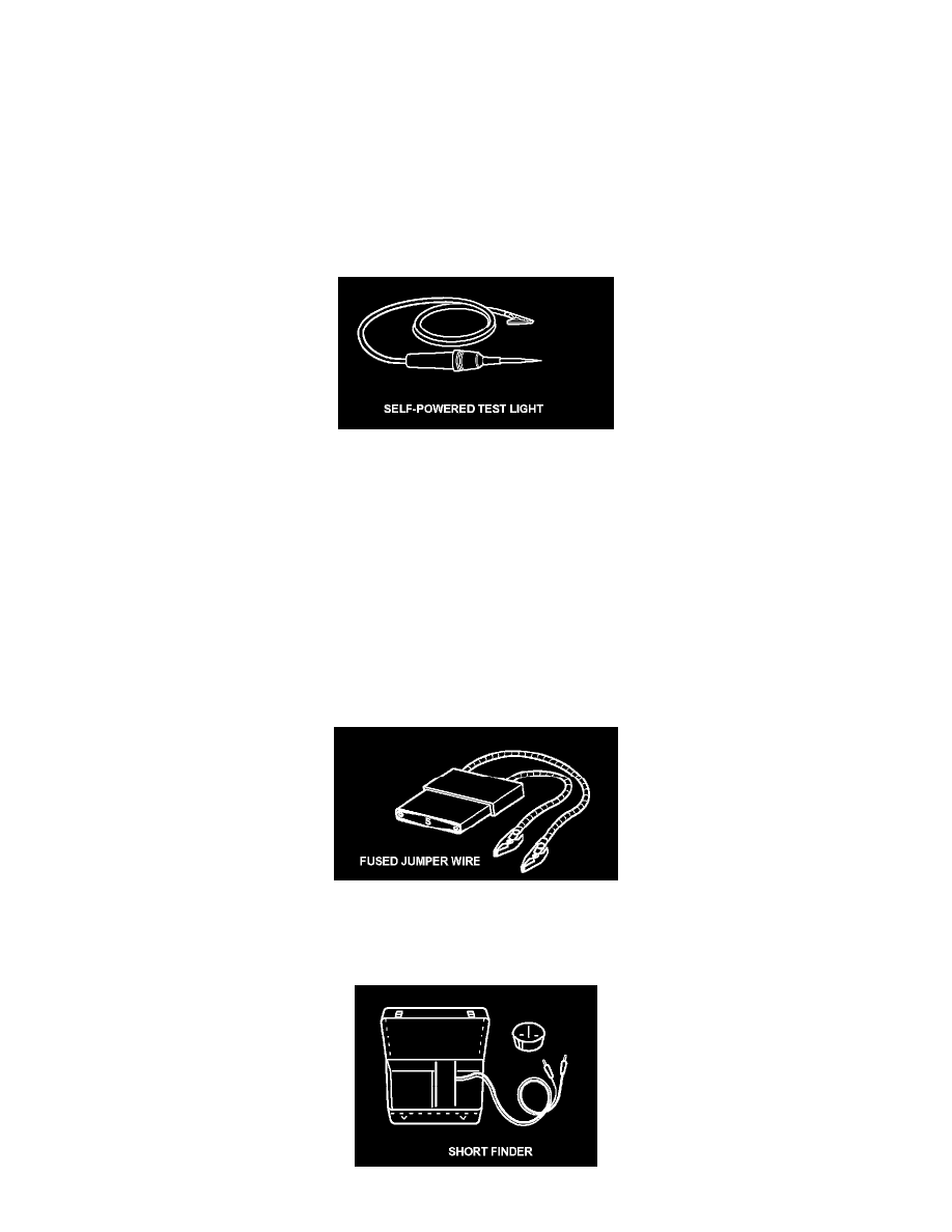
Self-Powered Test Light and DVOM
Use a self-powered test light to check for continuity. This tool is made up of a light bulb, battery, and two leads. To test it, touch the leads together: the
light should go on.
Use a self-powered test light only on an unpowered circuit. First, disconnect the battery, or remove the fuse that feeds the circuit you are working on.
Select two points in the circuit between which you want to check continuity. Connect one lead of the self-powered test light to each point. If there is
continuity, the test light's circuit will be completed, and the light will go on.
If, in addition, you need to know exactly how much resistance there is between two points, use a digital volt/ohmmeter (DVOM).
In the "OHMS" range, the DVOM will measure resistance between two points along a circuit. Low resistance means good continuity.
Diodes and solid-state devices in a circuit can make a DVOM give a false reading. To check a reading, reverse the leads, and take a second reading. If
the readings differ, the component is affecting the measurement.
Jumper Wire
Use a jumper wire to bypass an open circuit. A jumper wire is made up of an in-line fuse holder connected to a set of test leads. It should have a five
ampere fuse. Never connect a jumper wire across a short circuit. The direct battery short will blow the fuse.