
TL V6-3.2L (2004)
Voltage Signal: Testing and Inspection
Alternator FR Signal Circuit Troubleshooting
1. Start the engine, and let it idle.
2. Monitor the ALTERNATOR in the DATA LIST with the HDS.
3. Check if the indicated percentage varies when the headlight switch is on.
Does the percentage vary?
YES - The alternator signal circuit is OK.
NO - Go to step 4.
4. Turn the headlight switch and ignition switch OFF.
5. Disconnect the alternator 4P connector.
6. Turn the ignition switch ON (II).
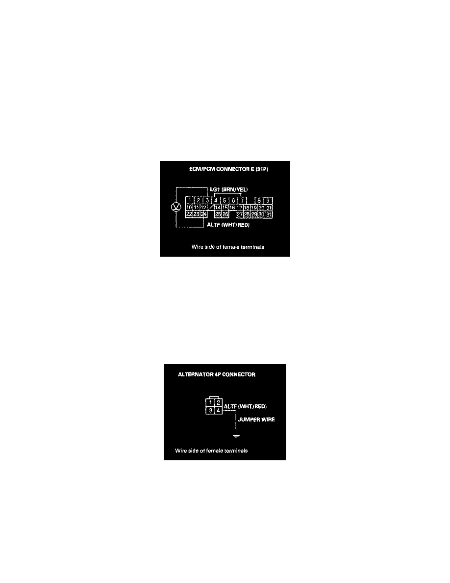
7. Measure voltage between ECM/PCM connector terminals E3 and E12.
Is there about 5 V?
YES - Go to step 8.
NO - Go to step 13.
8. Turn the ignition switch ON.
9. Jump the SCS line with the HDS.
10. Disconnect ECM/PCM connector E (31P).
11. Connect alternator 4P connector terminal No.4 to body ground with a jumper wire.