
TL AWD V6-3.7L (2010)
4. Pull down the lever (B) of the VSA modulator-control unit 47P connector, then confirm the connector is fully seated.
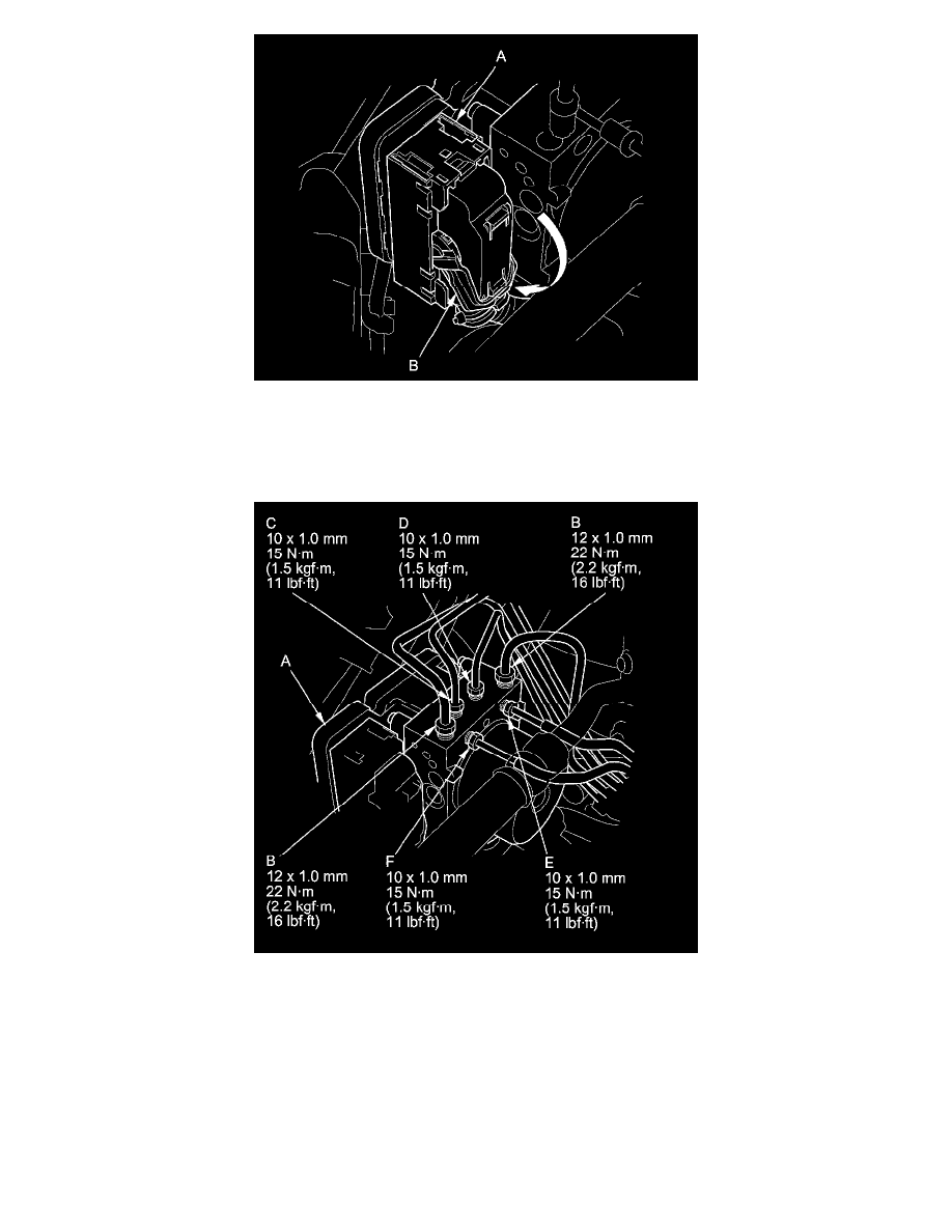
5. Connect the 10 mm brake lines and the 12 mm brake lines to the VSA modulator-control unit (A).
NOTE: Brake lines are connected to the master cylinder (B), the left-front (C), the right-front (D), the left-rear (E), and the right-rear (F) brake systems.
6. Install the suction line mounting bolt (A) to the bracket.