
TL FWD V6-3.5L (2009)
Information Bus: Initial Inspection and Diagnostic Overview
How to Troubleshoot the Multiplex Integrated Control System
Troubleshooting CAN Circuit Related Problems
NOTE: Check the PCM for DTCs and troubleshoot PCM See: Testing and Inspection/Initial Inspection and Diagnostic Overview or F-CAN loss of
communication errors first.
Using the HDS (Preferred method)
Connect the HDS to the Data Link Connector (DLC).
NOTE: There are two ways to read B-CAN code with the HDS.
First method; Go to B-CAN System Diagnosis Test Mode A to check for DTCs. See: Component Tests and General Diagnostics/Troubleshooting -
B-CAN System Diagnosis Test Mode A
Second method; Ground the SCS circuit with the HDS, then reed the DTCs displayed in the multi-information display (MID) in the gauge assembly, then
go to B-CAN System Diagnosis Test Mode A. See: Component Tests and General Diagnostics/Troubleshooting - B-CAN System Diagnosis Test Mode
A
Using the B-CAN System Diagnosis Test Mode 1 (Use only if the HDS is unavailable)
1. Check for communication circuit problems using B-CAN System Diagnostic Test Mode 1. See: Component Tests and General
Diagnostics/Troubleshooting - B-CAN System Diagnosis Test Mode 1 and Test Mode 2 (without the HDS)
2. Check for DTCs.
3. If there are DTCs stored, sort them, and then troubleshoot the DTCs in this order.
-1 Battery voltage DTCs
Internal error DTCs
-3 Loss of communication DTCs
NOTE: If DTC U1280 is stored, troubleshoot DTC U1280 first.
-4 Signal error DTCs
4. If no DTCs are retrieved, use B-CAN System Diagnostic Test Mode 2 to check all inputs related to the failure. See: Component Tests and General
Diagnostics/Troubleshooting - B-CAN System Diagnosis Test Mode 1 and Test Mode 2 (without the HDS)
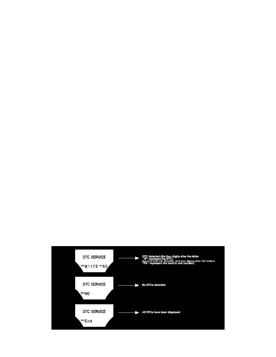
How to display DTCs on the MID of the gauge control module
Enter the B-CAN System Diagnosis Test Mode 1. See: Component Tests and General Diagnostics/Troubleshooting - B-CAN System Diagnosis Test
Mode 1 and Test Mode 2 (without the HDS) While in Test Mode 1, the DTCs which have been detected and stored individually by various B-CAN
(Body-controller Area Network) units will be shown one by one on the multi-information display when the communication between the MICU and the
gauge control module is normal. To scroll through the DTCs, press the SEL/RESET button.
The unit that has stored the code can be identified by the number shown on the multi-information display (MID).