
TL FWD V6-3.5L (2009)
Pressure Regulating Solenoid: Testing and Inspection
A/T Clutch Pressure Control Solenoid Valve A and B Test
A/T Clutch Pressure Control Solenoid Valve A and B Test
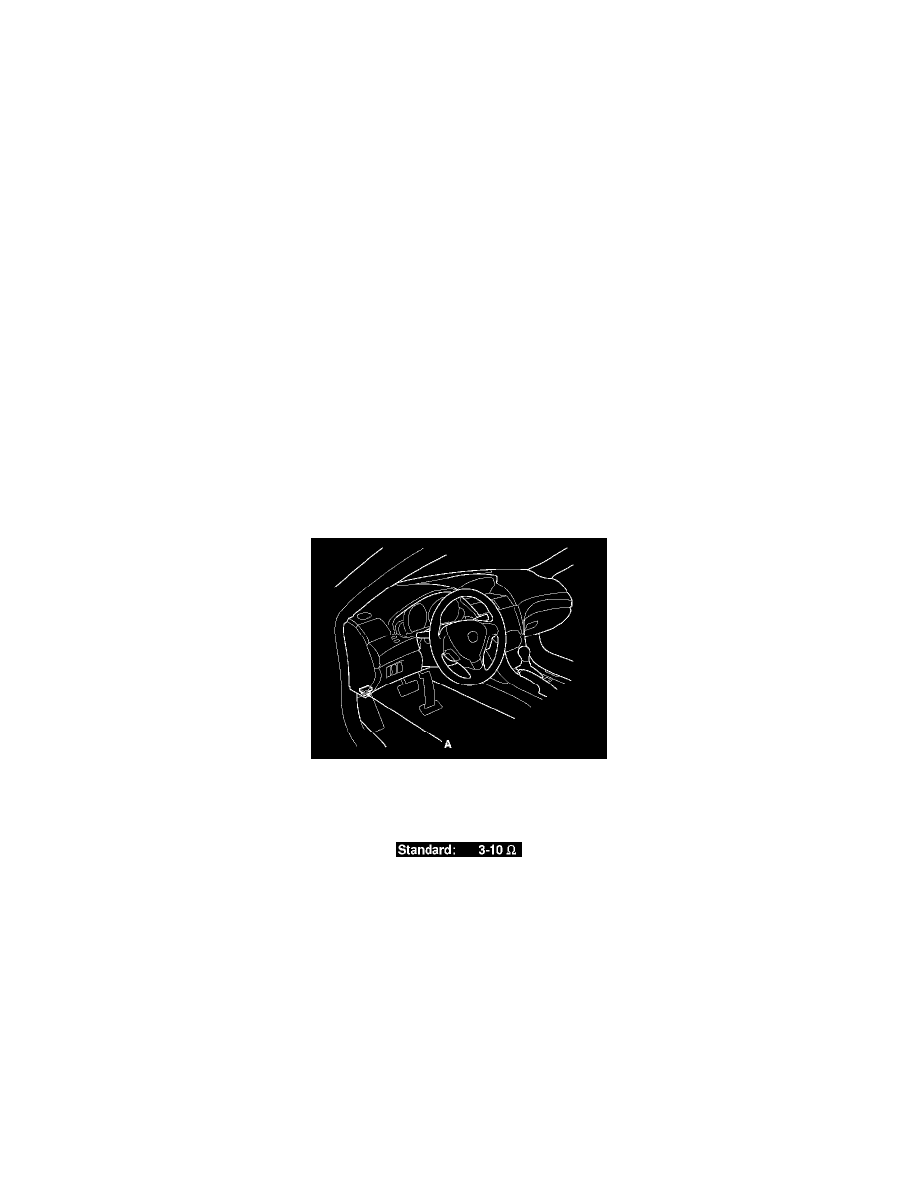
1. Connect the HDS to the DLC (A) located under the driver's side of the dashboard.
2. Turn the ignition switch to ON (II), or press the engine start/stop button to select the ON mode. Make sure the HDS communicates with the PCM.
If it does not, go to the DLC circuit troubleshooting. See: Powertrain Management/Computers and Control Systems/Testing and
Inspection/Component Tests and General Diagnostics/DLC Circuit Troubleshooting
3. Select Clutch Pressure Control (Linear) Solenoid Valve A or Clutch Pressure Control (Linear) Solenoid Valve B in the Miscellaneous Test Menu
with the HDS.
4. Test A/T clutch pressure control solenoid valve A or B with the HDS.
-
If the valve tests OK, the test is complete. Disconnect the HDS.
-
If the valve does not test OK, follow the instructions on the HDS.
-
If the valve does not test OK, and the HDS does not determine the cause, go to step 5.
5. Do the battery removal procedure. See: Starting and Charging/Battery/Service and Repair/Removal and Replacement
6. Remove the air cleaner assembly. See: Engine, Cooling and Exhaust/Engine/Tune-up and Engine Performance Checks/Air Cleaner
Housing/Service and Repair
7. Remove the battery base. See: Automatic Transmission/Transaxle/Service and Repair/Removal and Replacement/Automatic Transmission
Removal
8. Disconnect the A/T clutch pressure control solenoid valve A and B connectors.
9. Measure the A/T clutch pressure control solenoid valve A or B resistance at the connector terminals.
-
If the resistance is out of standard, replace A/T clutch pressure control solenoid valve A and B. See: Service and Repair/A/T Clutch Pressure
Control Solenoid Valve A and B Replacement
-
If the resistance is within the standard, go to step 10.
10. Connect a jumper wire from the negative battery terminal to solenoid valve A or B connector terminal No. 2, and connect another jumper wire
from the positive battery terminal to connector terminal No. 1.
-
If a clicking sound is heard, the valve is OK. Reconnect the connector, and install all removed parts.
-
If no clicking sound is heard, go to step 11.