
TSX L4-2.4L (2005)
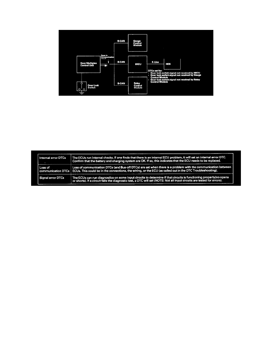
6. The door multiplex control unit transmits a door switch signal.
7. The multiplex integrated control unit (MICU), relay control module and gauge control module expect to receive the door lock switch signal, but
since there is a break in the communication circuits, it is not received.
8. Each ECU that expects to receive the door lock switch signal from the door multiplex control unit will transmit DTCs for the signal that it did not
receive.
Since there is a break in the communication circuit, the door lock switch signal could not be received by the gauge control module, multiplex
integrated control unit (MICU) or the relay control module. Each of these units will set "loss of communication" error codes for the signal(s) they
did not receive. There may be multiple communication DTCs if the unit that has become disconnected from the network would normally transmit
multiple messages during the communication line test. For example, the door multiplex control unit sends keyless panic signal and door lock
switch signal during the communication circuit test.
Diagnostic Trouble Codes
There are three DTC types used by the CAN networks.
Troubleshooting the CAN circuit related problems
NOTE: Check ECM/PCM for DTCs, and troubleshooting ECM/PCM F-CAN DTCs first.
Using the HDS (Preferred method)
1. Go to B-CAN System Diagnosis Test Mode A to check for "Connected units" and DTCs.
2. If no DTCs are retrieved, go to B-CAN System Diagnosis Test Mode C or D.
Without the HDS (Should be used only if HDS is unavailable)
3. Check for communication circuit problems using B-CAN System Diagnosis Test Mode 1.
4. Check for DTCs while in Mode 1.
5. Sort, and then troubleshoot the DTCs in the order below. Refer to the DTC troubleshooting for DTC descriptions.
1st.- Internal error and voltage failure DTCs
2nd.- Loss of communication DTCs
3rd.- Signal error DTCs
6. If no DTCs are retrieved, use B-CAN System Diagnosis Test Mode 2 to check all inputs related to failure.
Loss of Communication DTC cross-reference chart
When an ECU is unable to communicate with the other ECUs on the circuit, the other units will set loss of communication DTCs. Use this chart to find
the control unit that is not communicating.
7. Find the Transmitting Unit that is in the same row as all of the loss of communication DTCs retrieved.