
A1
|
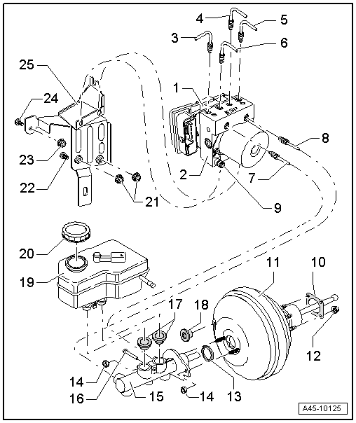
| 1 - | ABS control unit -J104- |
| q | With integral lateral acceleration sender -G200-, yaw rate sender -G202- and longitudinal acceleration sender -G251- |
| q | Removing and installing (vehicles with petrol engine) → Chapter |
| q | Removing and installing (vehicles with 1.4 ltr. TSI engine) → Chapter |
| q | Removing and installing (vehicles with TDI engine) → Chapter |
 Note
Note| The ABS control unit -J104- must not be separated from the ABS hydraulic unit -N55-. |
| 2 - | ABS hydraulic unit -N55- |
| q | ABS return flow pump -V39- and valve block must not be separated from each other |
| q | When renewing the hydraulic unit, always seal the old part with plugs from repair kit, Part No. 1H0 698 311 A |
| q | Removing and installing (vehicles with petrol engine) → Chapter |
| q | Removing and installing (vehicles with 1.4 ltr. TSI engine) → Chapter |
| q | Removing and installing (vehicles with TDI engine) → Chapter |
Note| The ABS control unit -J104- must not be separated from the ABS hydraulic unit -N55-. |
| 3 - | Brake line connection |
| q | Hydraulic unit to front right brake caliper |
| q | Marked on hydraulic unit with -VR- |
| q | 14 Nm |
| 4 - | Brake line connection |
| q | To rear right brake caliper/wheel brake cylinder |
| q | Marked on hydraulic unit with -HR- |
| q | 14 Nm |
| 5 - | Brake line connection |
| q | Hydraulic unit to front left brake caliper |
| q | Marked on hydraulic unit with -VL- |
| q | 14 Nm |
| 6 - | Brake line connection |
| q | To rear left brake caliper/wheel brake cylinder |
| q | Marked on hydraulic unit with -HL- |
| 7 - | Brake line connection |
| q | Brake master cylinder/primary piston circuit to hydraulic unit |
| q | Marked on hydraulic unit with -HZ1- |
| q | 14 Nm |
| 8 - | Brake line connection |
| q | Brake master cylinder/secondary piston circuit to hydraulic unit |
| q | Marked on hydraulic unit with -HZ2- |
| q | 14 Nm |
| 9 - | Hexagon nut |
| q | Rubber damper mounting |
| q | Hexagon nut with washer; turn back until rubber dampers can be turned |
| q | 8 Nm |
| 10 - | Gasket |
| q | For brake servo |
| 11 - | Brake servo |
| q | Functional check: |
| t | Switch off engine. |
| t | With the engine switched off, firmly depress the brake pedal several times (this reduces the vacuum present in the servo unit). |
| t | Then hold brake pedal in applied position employing moderate force and start engine. If the servo unit is working properly, the pedal will give slightly under foot (servo assistance becomes activated). |
| q | Separate from brake pedal before removing |
| q | If faulty, renew complete. |
| q | Adjusting ball head → Chapter |
| q | Removing and installing (vehicles with petrol engine) → Chapter |
| q | Removing and installing (vehicles with TDI engine) → Chapter |
Note| t | A heat shield is fitted on the brake master cylinder on some models. |
| t | Tightening torque for nuts: 20 Nm. |
| 12 - | Self-locking hexagon nut |
| q | 25 Nm |
| 13 - | Seal |
| q | Renew |
| 14 - | Self-locking hexagon nut |
| q | 25 Nm |
| 15 - | Brake master cylinder |
| q | Cannot be repaired If faulty, renew complete. |
| q | Removing and installing → Chapter |
| 16 - | Retaining pin for brake fluid reservoir |
| q | Insert through brake master cylinder |
| 17 - | Sealing plug |
| q | Moisten with brake fluid and press into brake master cylinder |
| 18 - | Sealing plug |
| q | Connection for vacuum hose |
| 19 - | Brake fluid reservoir |
| q | Removing and installing → Chapter |
| 20 - | Filler cap |
| – | With brake fluid level warning contact --F34-- |
| 21 - | Self-locking hexagon nut |
| q | 20 Nm |
| 22 - | Stud |
| q | Stud welded to body |
| 23 - | Self-locking hexagon nut |
| q | 20 Nm |
| 24 - | Stud |
| q | Stud welded to body |
| 25 - | Bracket |
|
|