| Tracing leaks in refrigerant circuit with leak detection system VAS 6201 |
| Vehicles with high-voltage system (hybrid vehicles) |

Note | t
| Certain leaks are difficult or even impossible to find using an electronic leak detector. In such cases, the leak detection system VAS 6201 can be used. |
| t
| Refrigerant circuit leaks result in a loss of refrigerant oil together with the refrigerant. This oil generally remains in the vicinity of the leak location. Adding a small quantity of fluorescent fluid to the refrigerant circuit makes this oil visible under UV light. The fluid (PAG oil containing an additive which shows up under UV light) is poured into the refrigerant circuit and becomes distributed with the refrigerant oil when the air conditioner is switched on. |
| t
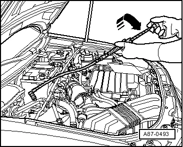
| The air conditioner must be operated for at least 60 min. to distribute the additive throughout the refrigerant circuit (the air conditioner compressor must run). Depending on the extent of the leak, the leakage location may already become visible under UV light within this period. |
| t
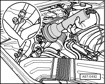
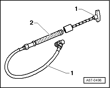
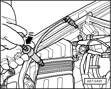
| The refrigerant oil containing the additive (which shows up under UV light) can either be poured directly into the open circuit or pumped in with the circuit charged using the hand pump VAS 6201/1 (from the leak detection system VAS 6201) via the service connection on the low-pressure end. |
| t
| If the UV leak detection additive is applied via the service connection on the low-pressure end with the refrigerant circuit charged, a small quantity of UV leak detection additive remains in the service connection. This is to be carefully removed so as to avoid subsequent erroneous leak detection. |
| t
| If a component forming part of a circuit into which the UV leak detection additive is poured has to be renewed, thoroughly clean the joints with the other components after assembling the refrigerant circuit. Otherwise, the residual UV leak detection additive at the joint could be erroneously identified as a leakage location during subsequent leak localisation. |
| t
| On discharging the refrigerant circuit, refrigeration oil and thus also UV leak detection additive ingresses into the air conditioner service station. The refrigerant oil is removed from the refrigerant in the oil separator of the air conditioner service station and discharged from the air conditioner service station via the drain. The refrigerant oil drained off is not to be poured back in. It is to be replaced with fresh refrigerant oil. |
| t
| Observe the following if leak detection fluid has already been poured into a refrigerant circuit in the course of previous repair work: Only add new leak detection fluid if refrigerant oil is renewed. If only a certain amount of refrigerant oil has been renewed, just add the corresponding quantity of leak detection fluid. After renewing 100 ml of refrigeration oil on a vehicle containing 250 ml for example, just add 1 ml (cm3) of UV leak detection additive. |
| t
| Certain materials and their compounds (e.g. oxidation products on aluminium components, anti-corrosion waxes) also show up under UV light. |
| t
| Certain types of air conditioner service station permit the direct introduction of the UV leak detection additive (heed the information given in the operating instructions of the air conditioner service station). |
| Proceed as follows with a completely empty refrigerant circuit to avoid allowing more refrigerant than is absolutely necessary for leak detection to escape into the environment when localising refrigerant circuit leaks: |
| –
| Evacuate the refrigerant circuit using the air conditioner service station → Chapter. |
Note | t
| If evacuation already reveals a major leak, this is to be located and eliminated as described → Chapter and → Chapter. |
| t
| With the leak detection system -VAS 6201-, it is also possible to add UV leak detection additive to a charged or open refrigerant circuit → Anchor. |
| Continue as follows if evacuation does not reveal any leakage or if the leakage is so slight that it is not possible to determine the leakage location on evacuation: |
| t
| Adding UV leak detection additive to the refrigerant circuit using the air conditioner service station → Anchor. |
| t
| Adding UV leak detection additive to the refrigerant circuit using the leak detection system -VAS 6201- → Anchor. |
| Adding UV leak detection additive to the refrigerant circuit using the air conditioner service station |
| –
| Adding UV leak detection additive and the specified quantity of refrigerant to the refrigerant circuit using the air conditioner service station → Chapter. |
Note | The quantity of UV leak detection additive to be added to a refrigerant circuit with a refrigeration oil quantity of 100 to 150 cm3 using the hand pump -VAS 6201- of the leak detection system -VAS 6201- is 2.5 +/- 0.5 cm3. If the quantity of refrigeration oil in the refrigerant circuit is greater, correspondingly more UV leak detection additive must be added (e.g. .5.0 +/- 0.5 cm3 for a refrigerant circuit with a refrigeration oil quantity of 250 cm3. When adding the UV leak detection additive with an air conditioner service station, the amount required may differ and attention must therefore be paid to the corresponding operating instructions. For the corresponding refrigeration oil quantity in the refrigerant circuit, refer to → Chapter. |
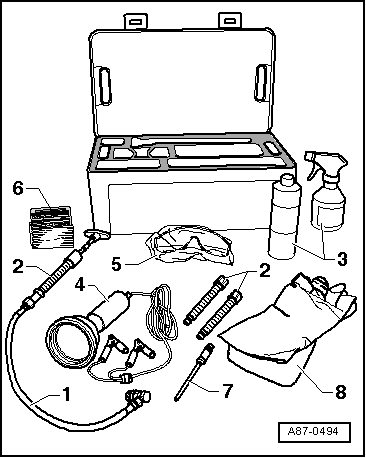
| Special tools and workshop equipment required |
|
|
|

 WARNING