audi Workshop Repair Guides

Audi Workshop Service and Repair Manuals

Removing and installing supplementary air heater elementZ35 > < Removing and installing fresh air blowerV2
Removing and installing heat exchanger
Special tools and workshop equipment required
t  Hose clamps up to 25 mm -3094-
t  Engine sealing plug set -VAS 6122-
t  Drip tray for workshop crane -VAS 6208-
t  Hose clip pliers -VAS 6362-
   
Removing
–  Place the drip tray for workshop crane -VAS 6208- under the engine.
–  Mark the arrangement of the coolant hoses.
–  Vehicles with petrol engine: Pinch off the coolant hoses -1- and -4- with hose clamps -3094- and detach from the heat exchanger by unfastening the hose clips -2, 3-.
  A80-10020
–  Vehicles with TDI engine: Remove the air cleaner housing → Rep. gr.23.
–  Pinch off the coolant hoses -1- and -4- with hose clamps -3094- and detach from the heat exchanger by lifting the retaining clips -2, 3-.
  A80-10012
–  Fit a short hose -2- on one connection.
l  Insert the compressed air gun -3- in the end of the hose.
–  Hold a vessel -4- under the second connection -1- and use the compressed air gun to carefully blow the coolant out of the heat exchanger.
  A80-10021
–  Screw out the bolt -2-.
–  Detach the adapter -1- from the connections of the heat exchanger.
–  Seal open lines and connections with clean plugs from the Engine sealing plug set -VAS 6122-.
  A80-10024
–  Move the front seats to the rearmost position.
–  Remove the centre console → Rep. gr.68.
–  Detach the insulation -1- if fitted.
  A87-10867
–  Detach the connecting collar -1- to the rear footwell vent.
  A87-10542
–  Vehicles with supplementary air heater element -Z35-: Unplug the connector -1- and remove from the holder. To do so, press aside the retainer -3- and pull the connector -2- in -arrow direction- out of the holder.
  A80-10013
–  Unscrew the nut -1- and lay bare the earth wire -2-.
  A87-10869
–  Protect the floor covering in the area beneath the heat exchanger with impermeable sheeting and absorbent paper.
–  If applicable, detach the cover panel -2- from the velcro strip.
–  Prise off -arrow- the retaining clips -1- all round.
  A80-10014
–  Release the bottom section -1- at the air distribution housing -2- downwards and take out to the right -arrow-.
–  Take the heat exchanger -3- out of the bottom section.
Installing
Install in reverse order, paying attention to the following:
l  Tightening torque (bolt at adapter for coolant hoses 8 Nm) → Chapter and → Chapter.
l  Tightening torque (bolt at earth connection to supplementary air heater element -Z35- 9 Nm → Current flow diagrams, Electrical fault finding and Fitting locations (fitting locations).
  Note
Replace the O-rings .
  A80-10015
Vehicles with heater:
–  Make sure the grommet -1- is correctly positioned in the bulkhead -2-.
  A80-10023
Vehicles with air conditioner:
–  Make sure the grommet -1- is correctly positioned in the bulkhead -2-.
All vehicles (continued):
–  Check the heater slot for contamination with the heat exchanger removed.
–  Remove any dirt or residual coolant.
–  Vehicles with TDI engine: Check the supplementary air heater element -Z35- for contamination and clean if necessary → Chapter.
  A87-10871
–  Check the foam seals -1, 3- attached to the heat exchanger -2- for damage and replace if necessary.
  Note
t  The foam seal may curl up on insertion if not correctly bonded on.
t  Cold air may flow past the heat exchanger if the foam seal is damaged or not properly fitted.
–  Insert the heat exchanger in the bottom section.
–  Position the bottom section at the heater and secure with the retaining clips.
  A80-10022
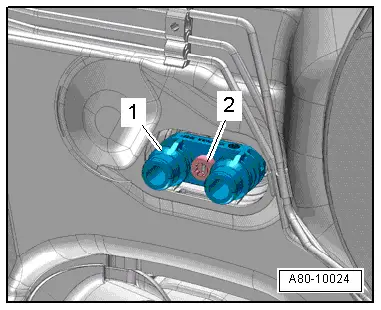
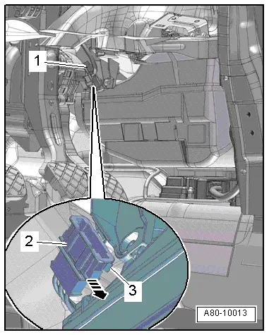
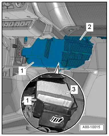
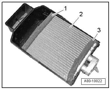
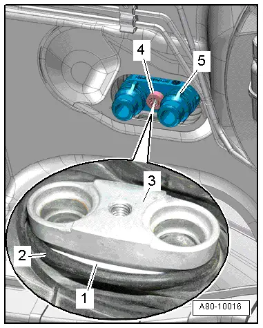
–  Make sure the grommet -2- is positioned in the groove -1- at the heat exchanger -3-.
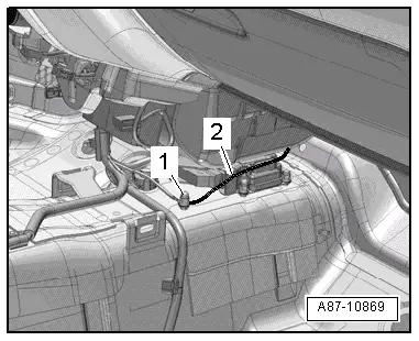
–  Press on the adapter -5- with new O-rings at the heat exchanger connections.
–  Tighten the bolt -4-.
  Note
t  
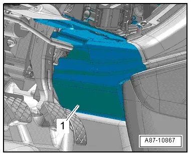
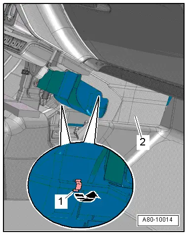
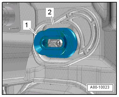
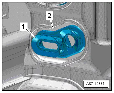
Make sure the grommet and heat exchanger at the bulkhead penetration are correctly positioned.
t  Water will ingress into the passenger compartment if the grommet is damaged or not correctly fitted.
–  Fill up with coolant and bleed in the specifed manner → Rep. gr.19.
  Note
t  When bleeding the coolant circuit, take special care to ensure complete bleeding of the heat exchanger. If air bubbles remain in the heat exchanger, complaints may be received about a lack of heat output in winter or differences in the temperature of the air flowing out of the vents with the same setting in control mode. Checking heat output: Heater → Chapter, manually controlled air conditioner → Chapter, automatically controlled air conditioner → Chapter.
t  
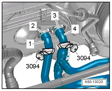
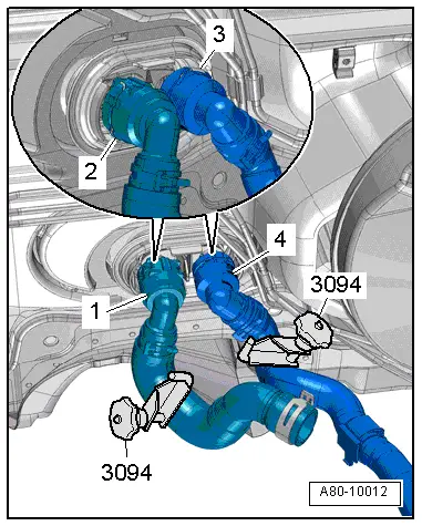
Depending on the vehicle equipment and engine, there is heat insulation on the coolant hoses; the insulation must not be damaged and must be re-attached after installation.
–  Install the centre console → Rep. gr.68.
–  Check operation of the heater, air conditioner.
  A80-10016

Removing and installing supplementary air heater elementZ35 > < Removing and installing fresh air blowerV2