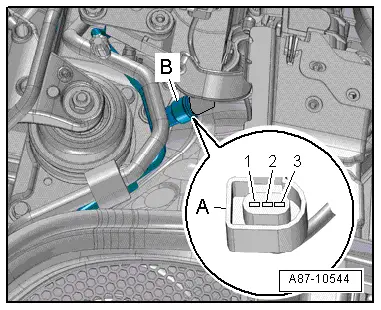
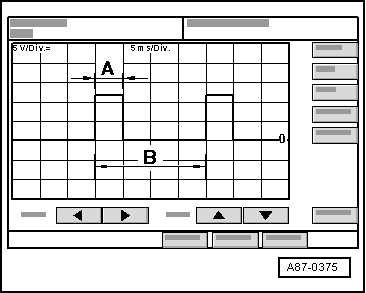
| Pressure signal from high-pressure sender -G65- |
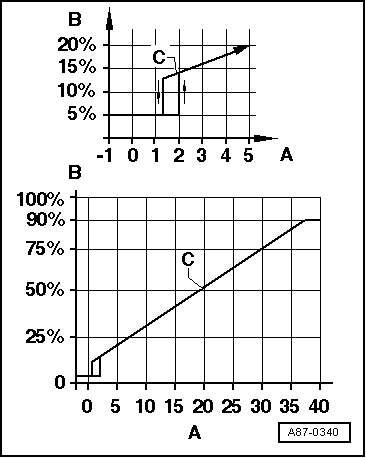
| A - | Pressure on high-pressure end of refrigerant circuit in bar (absolute pressure) |
| B - | Ratio of square-wave signal |
| C - | Characteristic curve for ratio of square-wave signal |

Note | t
| As soon as there is no air conditioner compressor shut-off criterion, the operating unit, Climatronic control unit -J255- / air conditioning system control unit -J301- switches on the air conditioner compressor (by actuating the air conditioner compressor regulating valve -N280-) → Vehicle diagnostic tester,
„Guided fault-finding“ function. |
| t
| If no other shut-off criterion is active, the air conditioner operating unit switches on the air conditioner compressor if the signal ratio is greater than approx. 12 % (corresponding to approx. 1.2 bar absolute pressure) and less than approx. 78 % (corresponding to approx. 32 bar absolute pressure). |
| t
| If the duty cycle is over 12 % (equivalent to approx. 1.2 bar absolute pressure) and below 78 % (equivalent to approx. 32 bar absolute pressure). |
| t
| If the signal ratio is less than 12 % or greater than 78 %, the air conditioner compressor is not switched on ( -N280- is not actuated). |
| t
| The signal ratio and the pressure calculated by the operating unit (calculated by control unit -J255- / -J301-) are displayed as measured value → Vehicle diagnostic tester,
„Guided fault-finding“ function. |
| t
| On the absolute pressure scale, 0 bar corresponds to an absolute vacuum. Normal ambient pressure thus corresponds to an absolute pressure of roughly 1 bar. On the scales of most pressure gauges, 0 bar corresponds to an absolute pressure of approx. 1 bar (can be seen from
„-1“ mark below
„0“). |
| t
| Depending on the pressure calculated in the refrigerant circuit with the air conditioner compressor actuated, the operating unit, -J255- / -J301- transmits the request for increased radiator fan -V7- speed via the data bus to the engine control unit, which actuates the radiator fan -V7- directly or by way of the radiator fan control unit -J293- (depending on version either at a specific pressure in the refrigerant circuit or as soon as the air conditioner compressor is switched on regardless of the pressure) → Current flow diagrams, Electrical fault finding and Fitting locations. The request determined by the operating unit, -J255- / -J301- is displayed as measured value → Vehicle diagnostic tester,
„Guided fault-finding“ function. |
| t
| Depending on the vehicle model, a radiator fan 2 -V177- may also be fitted → Rep. gr.19. |
| t
| At present, the request for actuation of the radiator fan -V7- is only transmitted on the data bus by the air conditioner operating unit, -J255- / -J301- as of a specific pressure in the refrigerant circuit. If the pressure in the refrigerant circuit is greater than approx. 9 bar (6 bar, if the pressure was previously in excess of 9 bar) and less than approx. 20 bar, between 30 and 100 % is requested depending on the pressure. |
| t
| If the pressure in the refrigerant circuit is less than approx. 9 bar (6 bar if the pressure was previously in excess of 9 bar), actuation of the radiator fan -V7- is currently not requested by the air conditioner operating unit, -J255- / -J301-. |
| t
| If the pressure in the refrigerant circuit is greater than approx. 20 bar, 100 % actuation of the radiator fan -V7- is requested at present by the air conditioner operating unit, -J255- / -J301- (the actual actuation may however be less than 100 % depending on the version of the engine control unit/ radiator fan control unit -J293-). |
| t
| The signal generated by the high-pressure sender -G65- is also used for engine control. The operating unit, -J255- / -J301- transmits the information via the data bus to the engine control unit (the torque required for driving the air conditioner compressor is governed by the pressure in the refrigerant circuit). Depending on the version of the engine control unit, the signal is displayed as signal ratio under
„Reading measured values“ (for the particular engine control unit fitted) → Vehicle diagnostic tester. |
|
|
|