
A1
| General view of heater |
| Component group „1“ - passenger compartment from the left |
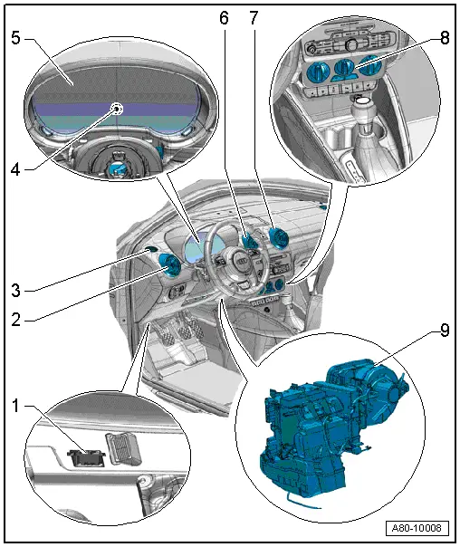
| 1 - | 16-pin connector -T16- - diagnostic connection |
| q | There is no provision for heater control unit -J65- self-diagnosis |
| 2 - | Dash panel vent (left-side) |
| q | Removing and installing → Rep. gr.70 |
| 3 - | Defroster vent for left side window |
| q | Removing and installing → Rep. gr.70 |
| 4 - | Ambient temperature indicator -G106- |
| q | Equipment-specific |
| q | Forms part of control unit in dash panel insert -J285- |
| q | If temperature display is incorrect, „read measured values“ of temperature sensor in „Guided fault-finding“ function → Vehicle diagnostic tester |
 Note
Note| The measured value of the ambient temperature sensor -G17- has no influence on heater and supplementary heater control on the TDI engine → Vehicle diagnostic tester, „Guided fault-finding“ function, TDI engine. |
| 5 - | Dash panel insert |
| q | With control unit in dash panel insert -J285-, ambient temperature indicator -G106- |
| q | The control unit in dash panel insert -J285- evaluates the measured value of the ambient temperature sensor -G17- and the ambient temperature calculated is displayed by the ambient temperature indicator -G106- |
| 6 - | Dash panel vent (centre left) |
| q | Removing and installing → Rep. gr.70 |
| 7 - | Dash panel vent (centre right) |
| q | Removing and installing → Rep. gr.70 |
| 8 - | Heater controls |
| q | With heater control unit -J65- |
| q | Removing and installing → Chapter |
| q | There is no provision for heater control unit -J65- self-diagnosis or „Guided fault-finding“ |
Note| The seat heating is not actuated via the heater control unit -J65-, but rather by way of two separate buttons. Checking → Rep. gr.74. |
| 9 - | Heater (viewed from left) |
| q | Block diagram of air distribution system → Chapter |
| q | Removing and installing → Chapter |
| q | Exploded view → Chapter |
| Component group „2“ - passenger compartment from the right |
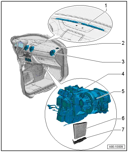
| 1 - | Windscreen defroster vent |
| q | Removing and installing → Rep. gr.70 |
| 2 - | Defroster vent for right side window |
| q | Removing and installing → Rep. gr.70 |
| 3 - | Dash panel vent (right-side) |
| q | Removing and installing → Rep. gr.70 |
| 4 - | Heater (viewed from right) |
| q | Block diagram of air distribution system → Chapter |
| q | Exploded view → Chapter |
| q | Removing and installing → Chapter |
| 5 - | Fresh air blower -V2- |
| q | Different versions → Electronic parts catalogue |
| q | Removing and installing → Chapter |
| 6 - | Dust and pollen filter |
| q | Different versions → Electronic parts catalogue |
| q | Observe replacement intervals → Maintenance tables |
| q | Removing and installing → Chapter |
| 7 - | Dust and pollen filter slot cover |