
A1
 Note
Note
|

| Special tools and workshop equipment required |
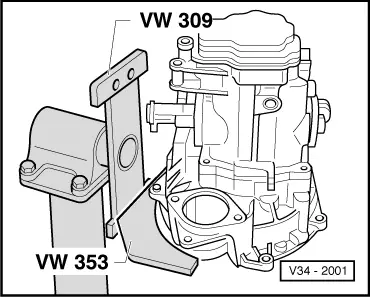
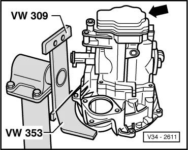
| t | Support plate -VW 309- |
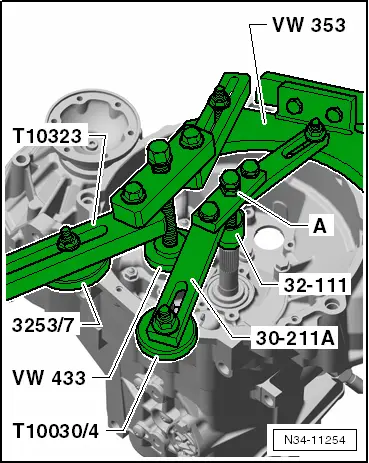
| t | Gearbox support -VW 353- |
| t | Drift -VW 295- |
| t | Drift sleeve -VW 244 B- |
| t | Hot air blower -V.A.G 1416- |
| t | Torque wrench -V.A.G 1331- |

| t | Support bridge -30-211A- |
| t | Thrust piece -32 - 111- |
| t | Thrust piece -T10030/4- |
| t | Thrust piece of assembly tool -T10030/4- |
| t | Tube -VW 416 B- |
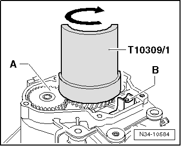
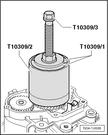
| t | Puller -T10309- |
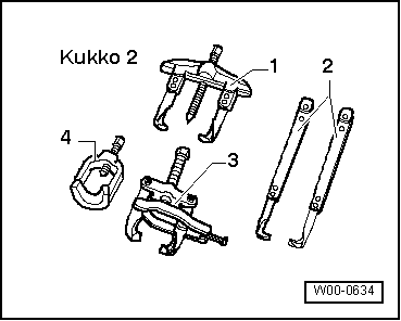
| t | Two-arm puller -T10040- |
| t | With claws -T10040/2A- |
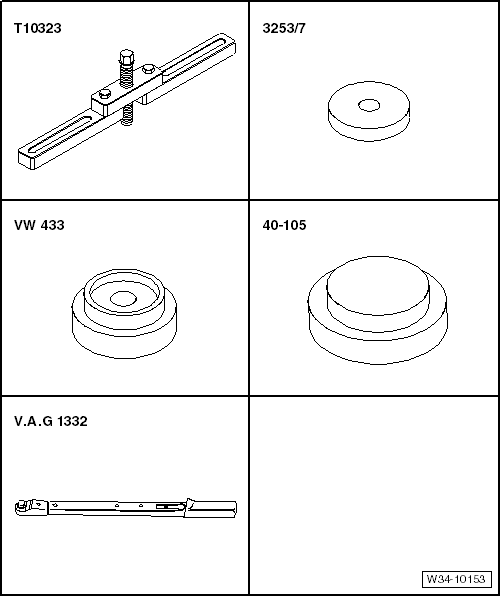
| t | Support bridge -T10323- |
| t | Assembly tool -3253/7- |
| t | Press tool -VW 433- |
| t | Thrust plate -40 - 105- |
| t | Torque wrench -V.A.G 1332- |
|
|
|
|
|
|
|
|
|
|
|
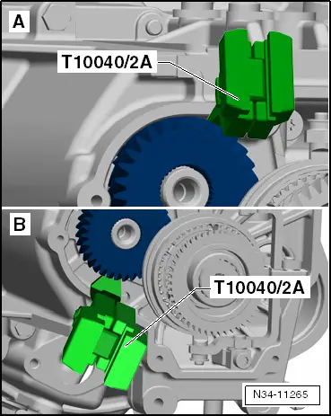
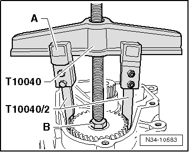
| If claws -T10040/2A- cannot be applied correctly: | |||||||
| -A- Claws -T10040/2A- foul against:
| In this case the 5th gear synchro-hub, 5th gear wheel and gearbox housing have to be removed together → Chapter. | ||||||
| -B- Claws -T10040/2A- foul against ribs in gearbox housing below gear wheel. | |||||||
| If claws -T10040/2A- can be applied correctly: | |||
| 5th gear can be removed separately → Fig. |
Note
|
|
|
|
|
|
Note
|
|