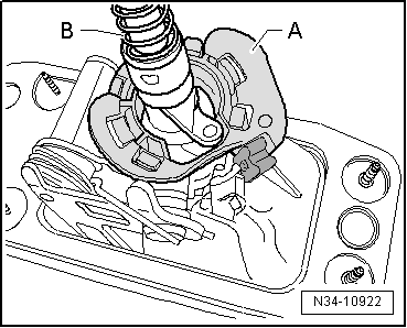
audi Workshop Repair Guides

Audi Workshop Service and Repair Manuals

Exploded view - gear selector cable and gate selector cable > < Removing and installing selector mechanism
Dismantling and assembling selector mechanism
Special tools and workshop equipment required
   
t  Thrust block -T10083-
  W00-1113
Dismantling
l  Selector mechanism removed → Chapter.
–  Detach retaining clips -2, 3-.
–  Press off gear selector cable -1- and gate selector cable -4- using a screwdriver.
  A34-10695
–  Lift top spring arm -A- over tab on gate selector lever.
–  Using a screwdriver, press lugs -arrows- on ball socket towards ball on gear lever guide; if necessary, break off lugs.
  N34-10921
–  Prise ball socket -A- out of selector mechanism together with gear lever guide and gear lever -B-.
–  Press ball socket -A- off ball on gear lever guide and remove.
  Note
  N34-10922
t  
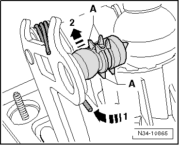
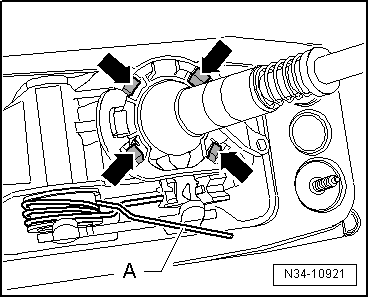
Note guides -A- when performing the following steps.
t  They must not break off.
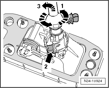
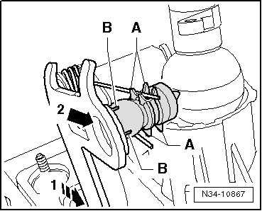
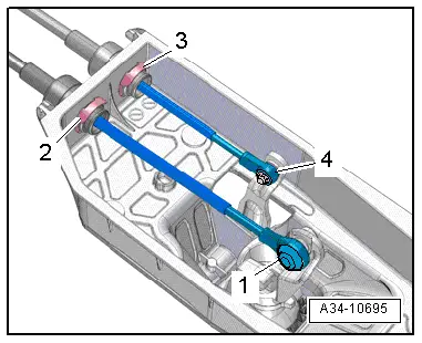
–  Swivel bottom spring arm -arrow 1- onto stop on shoulder of gate selector lever.
  Caution
Risk of injury
During the following steps, the bottom spring arm (-arrow 1-) can become dislodged and snap suddenly down off the shoulder of the gate selector lever.
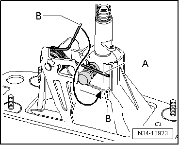
–  Pull gear lever guide upwards as far as stop and at the same time pull ball-head pin -arrow 2- out of gate selector lever.
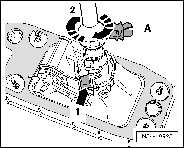
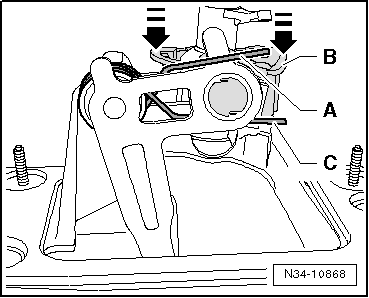
–  Press spring -arrow 1- carefully off the shoulder of the gate selector lever.
l  The spring arms will then compress „diagonally“.
  N34-10865
–  Turn gear lever guide anti-clockwise -arrow 1-.
l  The pin -arrow 2- should be positioned in the recess on the selector mechanism.
–  Swivel gear lever guide out in direction of -arrow 3- together with gear lever.
  N34-10924
Assembling
  Note
Renew ball socket.
–  Release the tension on spring arms -A- and -B-.
l  Spring arms -A- and -B- must point in opposite directions. (Shown here with gear lever guide installed.)
  N34-10923
–  Insert gear lever guide into selector mechanism together with gear lever.
l  Pin -arrow 1- should be positioned just inside recess on selector mechanism.
–  Turn gear lever guide in direction of -arrow 2- until ball-head pin -A- is above recess on selector mechanism.
  N34-10925
–  Carefully place selector mechanism on thrust block -T10083- together with gear lever guide.
l  The gear lever guide rests in the larger recess -arrow- in the thrust block -T10083-.
l  The gear lever guide should protrude out of the selector mechanism as far as the stop.
  N34-10869
–  Insert arm -A- of spring in guide from above.
–  Pull arm -B- of spring downwards and insert it next to the guide (towards ball head).
  Note
For illustration purposes, only part of the gate selector lever is shown.
–  Carefully take selector mechanism off thrust block -T10083- together with gear lever guide.
  N34-10923
–  Move gate selector lever back as far as stop -arrow 1-.
–  Grease ball-head pin and press it into hole on gate selector lever -arrow 2-.
l  Guides -A- and tabs -B- must not be damaged.
  N34-10867
–  Insert selector mechanism with gear lever guide in larger recess -arrow- in thrust block -T10083-.
l  The gear lever guide should protrude out of the selector mechanism as far as the stop.
  N34-10869
–  Lift top spring arm -A- over tab on gate selector lever.
–  Grease ball socket -B- and ball of gear lever guide.
–  Press ball socket onto ball of gear lever guide as far as stop.
–  Remove selector mechanism from thrust block -T10083-.
–  Press ball socket into selector mechanism in direction of -arrows-.
  N34-10868
l  All four lugs -arrows- must engage.
–  Lift top spring arm -A- over tab on gate selector lever and into guide.
–  Insert bottom spring arm into guide.
Further assembly is carried out in reverse sequence; note the following:
–  Install gear selector cable and gate selector cable → Chapter.
  N34-10921

Exploded view - gear selector cable and gate selector cable > < Removing and installing selector mechanism