
A1
| Exploded view - dismantling and assembling output shaft |
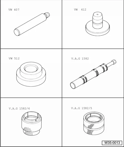
| Special tools and workshop equipment required |
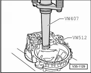
| t | Press tool -VW 407- |
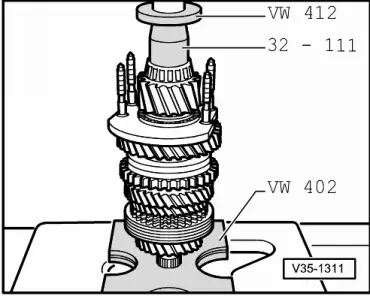
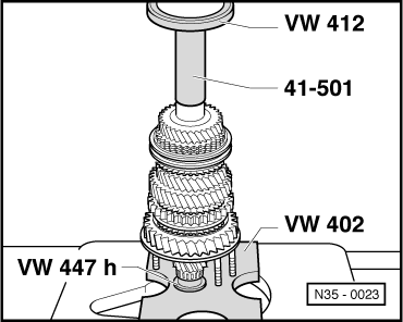
| t | Press tool -VW 412- |
| t | Thrust pad -VW 512- |
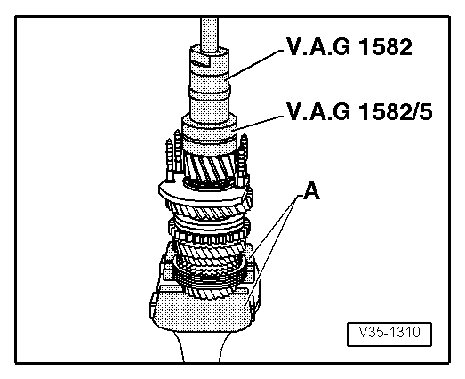
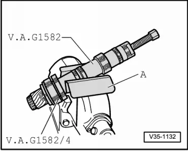
| t | Puller -V.A.G 1582- |
| t | Adapter -V.A.G 1582/4- |
| t | Adapter -V.A.G 1582/5- |
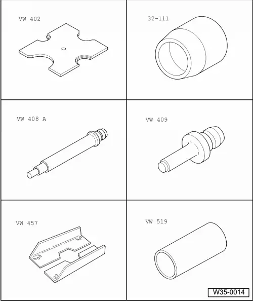
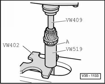
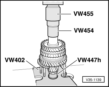
| t | Thrust plate -VW 402- |
| t | Thrust piece -32 - 111- |
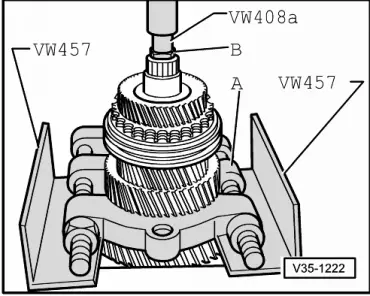
| t | Press tool -VW 408 A- |
| t | Press tool -VW 409- |
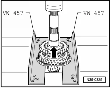
| t | Support rails -VW 457- |
| t | Tube -VW 519- |
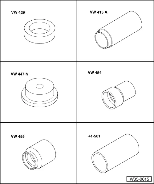
| t | Thrust ring -VW 429- |
| t | Tube -VW 415 A- |
| t | Thrust plate -VW 447 H- |
| t | Press tool -VW 454- |
| t | Installing sleeve -VW 455- |
| t | Drift sleeve -41-501- |
|
|
|
|
 Note
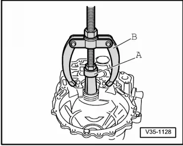
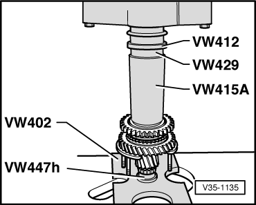
Note| t | The output shaft is dismantled as follows:- Position splitter under 2nd speed selector gear ( → Item) and press off as described in → Fig.. Remove circlip → Item. Then press off locking collar and synchro-hub for 1st and 2nd gear as shown in → Fig.. |
| t | Refer to → Electronic parts catalogue and technical data → Chapter when installing new gears or a new output shaft. |
| t | Always renew both tapered roller bearings together. |
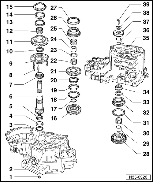
| 1 - | Nut |
| q | 25 Nm + 90° |
| q | 4 nuts for bearing mounting |
| q | Always renew |
| 2 - | Clutch housing |
| 3 - | Shim |
| q | For output shaft |
| q | Table of adjustments → Chapter |
| 4 - | Small tapered roller bearing outer race |
| q | Removing → Fig. |
| q | Pressing in → Fig. |
| 5 - | Small tapered roller bearing inner race |
| q | Pulling off → Fig. |
| q | Pressing on → Fig. |
| 6 - | Output shaft |
| q | Is paired with final drive gear, only renew as a set |
| q | Adjusting → Chapter |
| 7 - | Large tapered roller bearing inner race |
| q | Pulling off → Fig. |
| q | Pressing on → Fig. |
| 8 - | O-ring |
| q | Place O-rings (4x) on bolts for bearing mounting |
| 9 - | Bearing mounting |
| q | With large tapered roller bearing outer race and bolts |
| q | Only renew outer race together with large tapered roller bearing and bearing mounting |
| 10 - | Thrust washer |
| q | Shoulder on thrust washer faces towards tapered roller bearing |
| 11 - | 1st speed selector gear |
| 12 - | Needle bearing |
| q | For 1st gear |
| 13 - | Synchro-ring |
| q | (Inner ring for 1st gear) |
| q | Installation position → Fig. |
| q | Checking for wear → Fig. |
| q | Check lugs for scoring |
| 14 - | Outer ring for 1st gear |
| q | Installation position → Fig. |
| q | Checking for wear → Fig. |
| q | Renew if scored or if there are visible traces of wear |
| 15 - | 1st gear synchro-ring |
| q | Installation position → Fig. |
| q | Checking for wear → Fig. |
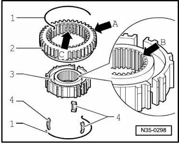
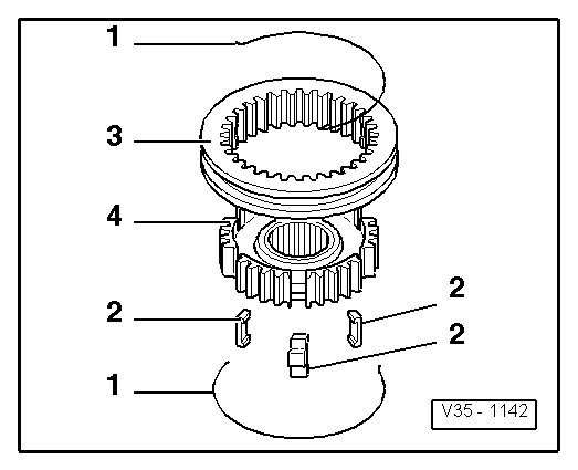
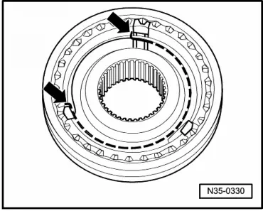
| 16 - | Locking collar with synchro-hub for 1st and 2nd gear |
| q | Press off together with bearing mounting → Item after removing circlip → Fig. |
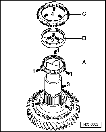
| q | Dismantling → Fig. |
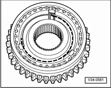
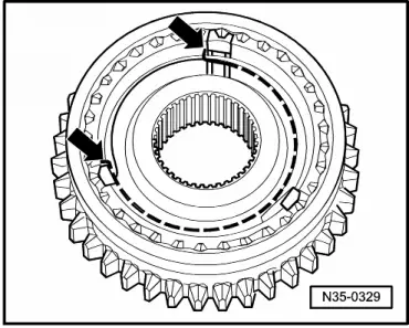
| q | Assembling locking collar/synchro-hub → Fig., → Fig. and → Fig. |
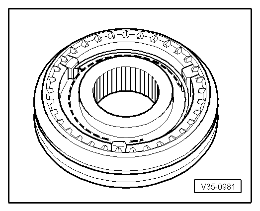
| q | Installation position → Fig. |
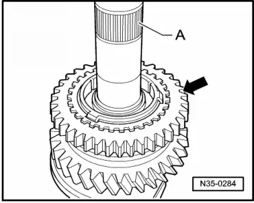
| q | Pressing on → Fig. |
| 17 - | Circlip |
| 18 - | 2nd gear synchro-ring |
| q | Checking for wear → Fig. |
| q | Assemble so that the recesses engage on the locking pieces on the locking collar → Item |
| 19 - | Outer ring for 2nd gear |
| q | Insert in synchro-ring → Item |
| q | Installation position → Fig. |
| q | Renew if scored or if there are visible traces of wear |
| 20 - | Synchro-ring |
| q | (Inner ring for 2nd gear) |
| q | Checking for wear → Fig. |
| q | Check lugs for scoring |
| q | Installation position → Fig. |
| 21 - | 2nd speed selector gear |
| q | Installation position → Fig. |
| 22 - | Needle bearing |
| q | For 2nd gear |
| 23 - | Thrust washer |
| 24 - | Sleeve for 3rd gear needle bearing |
| q | Pressing off with 2nd speed selector gear → Fig. |
| q | Pressing on → Fig. |
| 25 - | Needle bearing |
| q | For 3rd gear |
| 26 - | 3rd speed selector gear |
| 27 - | 3rd gear synchro-ring |
| q | Checking for wear → Fig. |
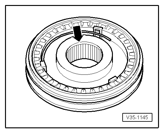
| 28 - | Locking collar with synchro-hub for 3rd and 4th gear |
| q | Pressing off with 2nd speed selector gear → Item and 3rd speed selector gear → Item → Fig. |
| q | Dismantling → Fig. |
| q | Assembling locking collar/synchro-hub → Fig., → Fig. and → Fig. |
| q | Installation position: Locking collar/synchro-hub → Fig. |
| q | Pressing on → Fig. |
| 29 - | Sleeve |
| q | For needle bearing |
| q | Pressing off with locking collar and synchro-hub for 3rd and 4th gear → Item → Fig. |
| q | Pressing on → Fig. |
| 30 - | Needle bearing |
| q | For 4th gear |
| 31 - | 4th gear synchro-ring |
| q | Checking for wear → Fig. |
| 32 - | 4th speed selector gear |
| 33 - | Thrust washer |
| 34 - | Needle bearing |
| q | For output shaft |
| q | Removing and installing → Fig. |
| 35 - | Gearbox housing |
| 36 - | Sleeve |
| q | For needle bearing/output shaft |
| q | Pressing off → Fig. |
| q | Pressing on → Fig. |
| 37 - | 5th gear wheel |
| q | Pulling off individually → Chapter |
| q | Pulling off together with gearbox housing → Chapter |
| 38 - | Dished spring |
| q | Installation position → Fig. |
| 39 - | Bolt |
| q | Tightening torque → Item |
| q | Always renew |
| q | Fitted piece on bolt head holds dished spring in position → Fig. |
| q | Removing and installing → Chapter |
|
|
|
|
|
|
|
|
|
|
|
|
|
|
Note
|
|
|
|
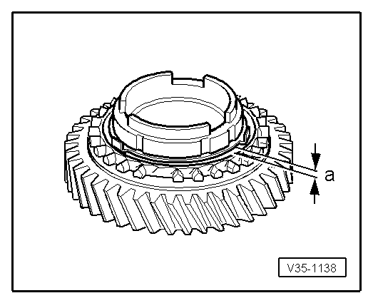
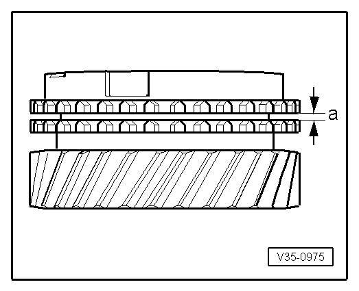
| Gap -a- | Installation depth | Wear limit |
| 1st and 2nd gear | 0.75…1.25 mm | 0.3 mm |
|
|
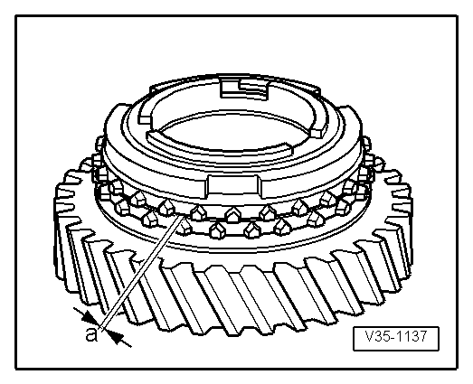
| Gap -a- | Installation depth | Wear limit |
| 1st and 2nd gear | 1.2…1.8 mm | 0.5 mm |
|
|
|
|
|
|
|
|
|
|
|
|
|
|
|
|
|
|
|
|
| Gap -a- | Installation depth | Wear limit |
| 1st gear 3rd gear 4th gear | 1.0…1.7 mm 1.0…1.7 mm 1.0…1.7 mm | 0.5 mm |
|
|
|
|
|
|
|
|
|
|
|
|
|
|