
A1
| Exploded view - input shaft |
 Note
Note| t | Refer to → Electronics parts catalogue and technical data when installing new gear wheels or a new input shaft. |
| t | Pressing input and output shaft out of bearing mounting and grooved ball bearings → Chapter |
| t | Lubricate all bearings, selector gears and synchro-rings on input shaft with gear oil before installing. |
| t | Do not interchange synchro-rings. When re-using synchro-rings, always fit on the same selector gear. |
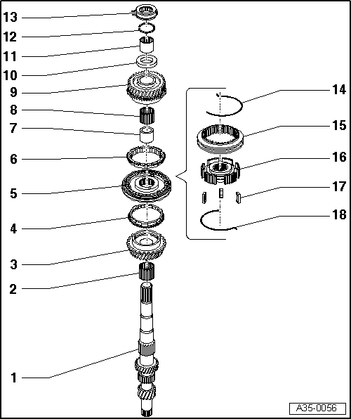
| 1 - | Input shaft |
| 2 - | Needle bearing |
| q | For 3rd gear |
| 3 - | 3rd speed selector gear |
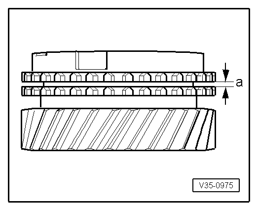
| 4 - | 3rd gear synchro-ring |
| q | Checking for wear → Fig. |
| 5 - | Locking collar with synchronising hub for 3rd and 4th gear |
| q | Removing and installing → Chapter |
| q | Dismantling and assembling → |
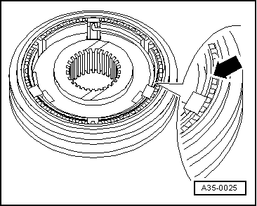
| q | Installation position: Locking collar/synchronising hub → Fig. |
| 6 - | 4th gear synchro-ring |
| q | Checking for wear → Fig. |
| q | Checking for wear → Fig. |
| 7 - | Sleeve |
| q | For 4th gear needle bearing |
| q | Removing and installing → Chapter |
| q | Renew together with → Item |
| 8 - | Needle bearing |
| q | For 4th gear |
| q | Removing and installing → Chapter |
| q | Renew together with → Item |
| 9 - | 4th speed selector gear |
| 10 - | Thrust washer |
| 11 - | Inner race for roller bearing |
| q | Removing and installing → Chapter |
| 12 - | Circlip |
| q | Renew |
| q | Determining thickness → Anchor |
| 13 - | Roller bearing |
| q | With circlip |
| q | Removing and installing → Chapter |
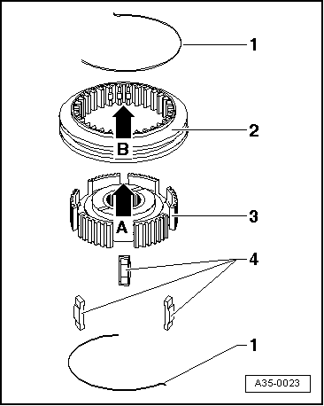
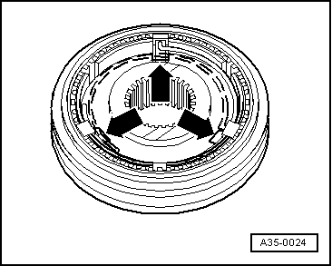
| 14 - | Spring |
| q | Installation position: angled end of spring must locate in one of the locking pieces. |
| 15 - | Locking collar for 3rd and 4th gear |
| q | Dismantling and assembling → |
| q | Installation position: Locking collar/synchronising hub → Fig. |
| 16 - | Synchronising hub for 3rd and 4th gear |
| 17 - | Locking pieces |
| q | 3x |
| 18 - | Spring |
| q | Installation position: angled end of spring must locate in one of the locking pieces. |
|
|
| Gap -a- | Installation depth | Wear limit |
| 3rd and 4th gear | 1.1 ... 1.7 mm | 0.5 mm |
|
|
|
|