audi Workshop Repair Guides

Audi Workshop Service and Repair Manuals

Checking oil level in manual gearbox > < Removing and installing pendulum support
Removing and installing gearbox bracket
Special tools and workshop equipment required
   
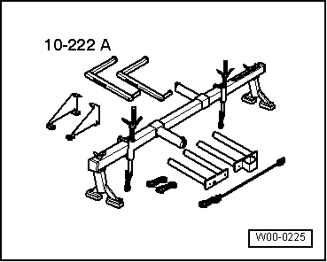
t  Support bracket -10 - 222 A-
  W00-0225
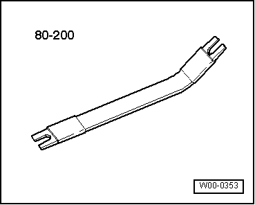
t  Removal lever -80 - 200-
  W00-0353
Removing
  Note
Re-attach all cable ties at the same locations when re-installing.
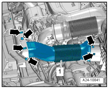
–  Release catches -arrows- and detach air duct -1-.
  A24-10841
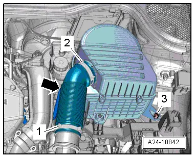
–  Release hose clip -1- and disconnect air hose from connection.
–  Detach vacuum hose -arrow- from air hose.
–  Remove bolt -3- and detach air cleaner housing.
  Note
-Item 2- can be disregarded.
  A24-10842
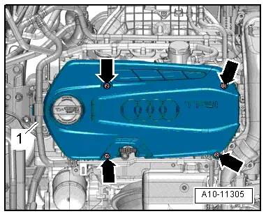
–  Move clear coolant hose -1-.
–  Unscrew bolts -arrows- and detach engine cover panel.
  A10-11305
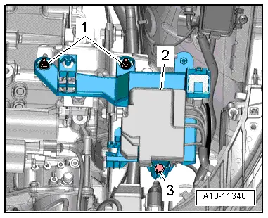
–  Remove nuts -1- and bolt -3- and press electronics box -2- to one side.
  A10-11340
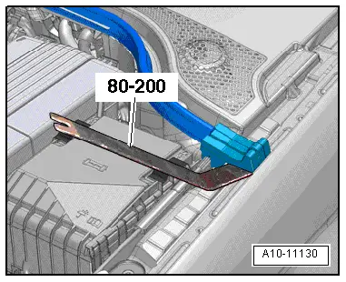
–  Lever clips off sealing elements using removal lever -80 - 200- and detach sealing elements on both sides.
  A10-11130
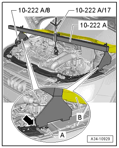
–  Set up support bracket -10 - 222 A- on wing mounting flanges, as shown in illustration.
l  Position both adapters -10 - 222 A /8- behind lock carrier connection -arrow- and next to bolts -A-.
l  Plenum chamber cover -B- will now rest on adapters -10 - 222 A /8-.
–  Hook spindle of support bracket into engine lifting eye (left-side).
–  Take up weight of engine with spindle; do not lift.
–  Raise vehicle.
–  Remove front left wheel.
  A34-10929
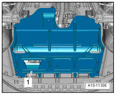
–  Remove noise insulation -1- → General body repairs, exterior; Rep. gr.66.
–  Remove wheel housing liner (front left) → General body repairs, exterior; Rep. gr.66.
  A10-11306
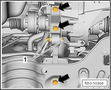
  WARNING
Risk of accident.
The bolted connection -1- must not be slackened.
–  Remove bolts -arrows- and detach pendulum support.
  N10-10308
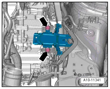
–  Remove bolts -arrows- from gearbox mounting.
  A10-11341
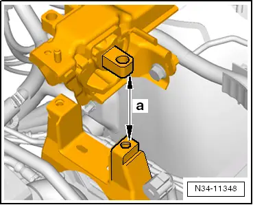
–  Lower engine/gearbox assembly using spindle of support bracket -10 - 222 A- until distance -a- is obtained between gearbox bracket and gearbox mounting.
l  Dimension -a- = 50 mm
l  Gearbox must not make contact with subframe in area of differential.
l  Bolts -arrows- securing gearbox bracket -A- must be accessible.
  N34-11348
l  Pay attention to coolant hoses between engine and heat exchanger for heating system.
–  Detach gearbox bracket -A- from gearbox -arrows-.
Installing
Installation is carried out in reverse sequence; note the following:
l  Tightening torques → Chapter „Exploded view - assembly mountings“
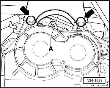
  N34-1528
–  Fit gearbox bracket -A- with new bolts -arrows-.
  Note
t  Renew bolts which are tightened by turning through a specified angle.
t  Lubricate rubber mounting of assembly mounting (left-side) and upper part of gearbox bracket with assembly oil → Electronic parts catalogue.
–  Raise engine/gearbox assembly via spindle of support bracket -10 - 222 A-.
  N34-1528
–  Align the engine/gearbox assembly in installation position. To do so, raise engine/gearbox until gearbox bracket makes full contact with gearbox mounting.
  Caution
The threads in the gearbox bracket can be damaged if the bolts are not inserted straight.
Before fitting the bolts -arrows-, the gearbox bracket and the gearbox mounting must be aligned so they are parallel. If necessary, press gearbox up with engine and gearbox jack.
–  Check adjustment of assembly mountings; adjust if necessary → Engine, mechanics; Rep. gr.10.
–  Bolt gearbox bracket to gearbox mounting.
  WARNING
Do not remove support bracket -10 - 222 A- until all bolts securing the left-hand engine/gearbox mounting have been tightened to the specified torque.
–  Install pendulum support → Chapter.
–  Install wheel housing liner (front left) and noise insulation → General body repairs, exterior; Rep. gr.66.
–  Fit front left wheel → Running gear; Rep. gr.40.
–  Install air cleaner housing → Injection and ignition system; Rep. gr.24.
  A10-11341

Checking oil level in manual gearbox > < Removing and installing pendulum support