
A1
| Camshaft timing chain - exploded view |
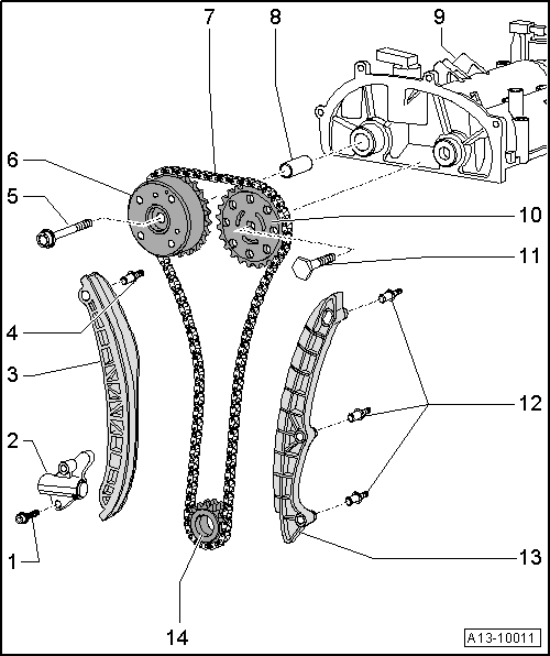
| 1 - | Bolt |
| q | 9 Nm |
| 2 - | Chain tensioner |
| q | Exerts spring pressure |
| q | Before removing, lock in place using locking pin -T40011- |
| 3 - | Tensioning rail |
| 4 - | Guide pin |
| q | 18 Nm |
| 5 - | Bolt |
 Caution
|
| q | Renew |
| q | When loosening and tightening, lock camshaft chain sprocket using counterhold tool -T10172- |
| q | 40 Nm + 90° further |
| 6 - | Camshaft adjuster |
| q | For inlet camshaft |
| q | Do not dismantle |
| q | Removing and installing → Chapter |
| 7 - | Camshaft timing chain |
| q | Before removing, mark running direction with paint |
| q | Removing and installing → Chapter |
| 8 - | Bearing bush |
| q | For camshaft adjuster |
| 9 - | Camshaft housing |
| q | Removing and installing → Chapter |
| 10 - | Camshaft chain sprocket |
| q | For exhaust camshaft |
| q | Removing and installing → Chapter |
| 11 - | Bolt |
| q | Renew |
| q | When loosening and tightening, lock camshaft chain sprocket using counterhold tool -T10172- |
| q | 50 Nm + 90° further |
| 12 - | Guide pin |
| q | 18 Nm |
| 13 - | Guide rail |
| q | Removing and installing → Chapter |
| 14 - | Chain sprocket |
| q | For drive chain for oil pump and camshaft timing chain |
| q | Push-fitted onto crankshaft |
| q | To remove or install → Chapter „Removing and installing camshaft timing chain“ and → Chapter „Removing and installing oil pump“ |
| q | Installation position → Fig. |
| q | Contact surfaces must be free of oil or grease |