
Camshaft Timing Chain Replacement for 4-Cylinder Petrol Engine
| Removing and installing camshaft timing chain |
| Special tools and workshop equipment required |
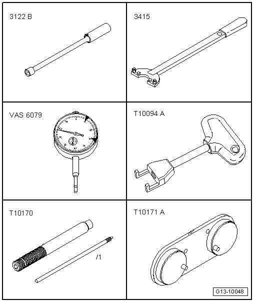
| t | Spark plug socket and extension -3122 B- |
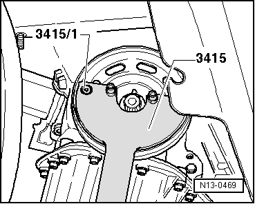
| t | Counterhold tool -3415- with pins -3415/1- |
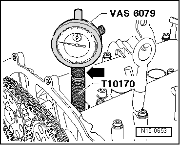
| t | Dial gauge -VAS 6079- |
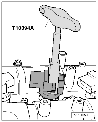
| t | Puller -T10094 A- |
| t | Adapter for dial gauge -T10170- |
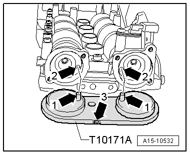
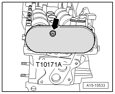
| t | Camshaft clamp -T10171 A- |
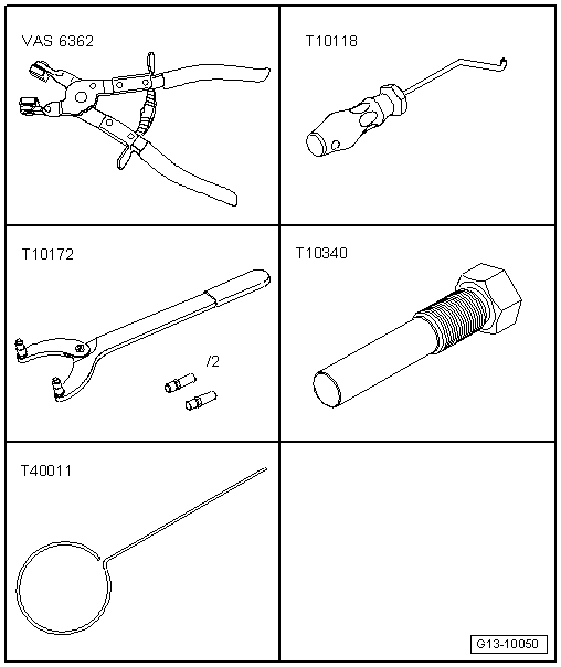
| t | Hose clip pliers -VAS 6362- |
| t | Assembly tool -T10118- |
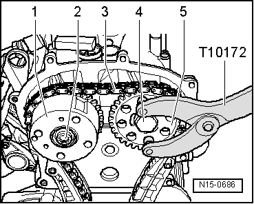
| t | Counterhold tool -T10172- |
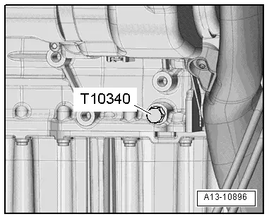
| t | Locking pin -T10340- |
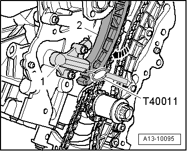
| t | Locking pin -T40011- |
|
|
|

|
|
|
|
|
 Note
Note
|
|
|
|
|
|
|
|
|
|
|
|
|
|
|
|
|
|
|
|
 Caution
|
|
Note
|
|
|
|
|
|
|
|
Note
Note
|
|
|
|
|

|
|
|
Note
|
|
Note
|
|
Note
|
|
|
|
|
|
Note
|
|
Note
|
|