audi Workshop Repair Guides

Audi Workshop Service and Repair Manuals

Removing and installing thermostat > < Removing and installing coolant pump
Removing and installing 4/2-way valve
Special tools and workshop equipment required
   
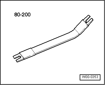
t  Removal lever -80 - 200-
  W00-0353
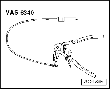
t  Hose clip pliers -VAS 6340-
  W00-10380
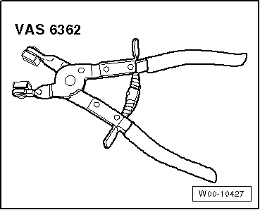
t  Hose clip pliers -VAS 6362-
  W00-10427
Removing
–  Drain coolant → Chapter.
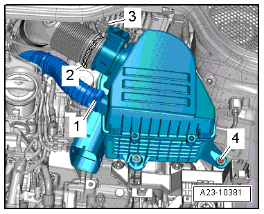
–  Remove air cleaner housing → Rep. gr.23.
  A23-10381
–  Version for countries with cold climates: Unplug electrical connector -2-.
–  Press release tabs and disconnect crankcase breather hose -1-.
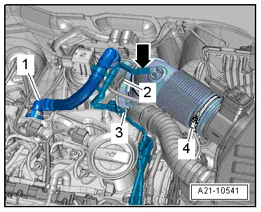
–  Disconnect vacuum hose -arrow-.
–  Remove bolt -3-, swivel air pipe with connection to rear and detach from turbocharger.
  Note
Disregard -item 4-.
  A21-10541
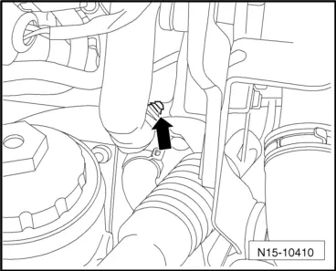
–  Unclip wiring harness from retainer -arrow-.
  N15-10410
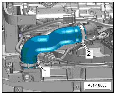
–  Release hose clips -1- and -2- and remove air hose.
  A21-10550
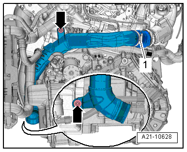
–  Remove bolts -arrows-.
–  Using removal lever -80 - 200-, move clear electrical wiring and hoses at air pipe (left-side).
–  Loosen hose clip -3- and detach air pipe (left-side).
  A21-10628
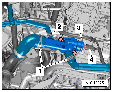
–  Release hose clips -1-, detach coolant hoses and move clear.
  Note
Disregard -items 2, 3, 4-.
  A19-10975
–  Take electrical connector -1- for Hall sender -G40- out of retainer.
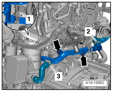
–  Remove bolts -arrows-, pull off coolant pipe (front) from 4/2-way valve to left side and leave in installation position.
  Note
Disregard -items 2, 3-.
  A19-10993
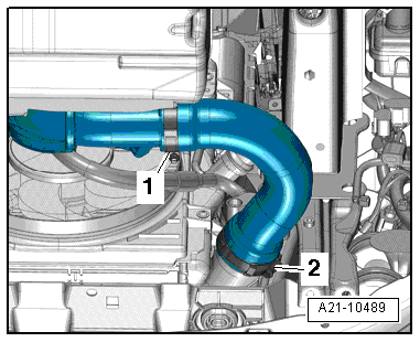
–  Release hose clips -1- and -2- and remove air hose.
–  Seal off open pipes/lines and connections with clean plugs from engine bung set -VAS 6122-.
  A21-10489
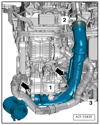
–  Remove bolts -arrows-.
–  Move coolant hose -3- clear.
–  Loosen hose clip -2-.
–  Unplug electrical connector -1- at charge pressure sender -G31-/intake air temperature sender -G42- and detach air pipe (right-side).
  A21-10435
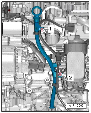
–  Pull oil dipstick out slightly and remove bolt -1-.
–  Release clip -2- with removal lever -80 - 200-.
–  Pull guide tube for oil dipstick upwards out of cylinder block and push to one side.
  A17-10509
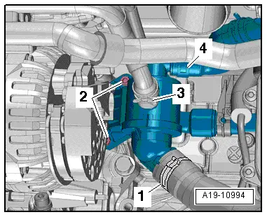
–  Remove bolts -2-.
–  Loosen hose clips -1, 3, 4-, detach coolant hoses and remove 4/2-way valve with thermostat.
Installing
l  Tightening torque → Chapter „Coolant pump and thermostat - exploded view“
Installation is carried out in the reverse order; note the following:
–  Install dipstick guide tube → Chapter.
–  Install coolant pipe (front) → Chapter.
–  Install air pipes → Chapter.
–  Install intake connecting pipe → Chapter.
–  Electrical connections and routing → Current flow diagrams, Electrical fault finding and Fitting locations.
–  Install battery mounting and battery → Electrical system; Rep. gr.27.
–  Install air cleaner housing → Rep. gr.23.
–  Install air hoses with screw-type clips → Fig..
–  Fill up with coolant → Anchor.
  A19-10994

Removing and installing thermostat > < Removing and installing coolant pump