audi Workshop Repair Guides

Audi Workshop Service and Repair Manuals

Checking compression > < Cylinder head - exploded view
Removing and installing cylinder head
   
Removing and installing cylinder head
Special tools and workshop equipment required
t  Removal lever -80 - 200-
t  Diesel injection pump locking pin -3359-
t  Engine bung set -VAS 6122-
t  Counterhold tool -T10051-
t  Puller -T10052-
t  Bit XZN 10 -T10385-

   
Removing
–  Drain coolant → Chapter.
–  Remove air cleaner housing → Rep. gr.23.
–  Remove plenum chamber partition panel → Rep. gr.50.
  A23-10381
–  Version for countries with cold climates: Unplug electrical connector -2-.
–  Press release tabs and disconnect crankcase breather hose -1-.
–  Disconnect vacuum hose -arrow-.
–  Remove bolt -3-, swivel air pipe with connection to rear and detach from turbocharger.
  Note
Disregard -item 4-.
  A21-10541
–  Detach vacuum hose -2- from vacuum unit of turbocharger.
–  Disconnect vacuum hose -3-.
  Note
Disregard -item 1-.
  A21-10338
–  Release hose clips -1- and -2- and remove air hose.
  A21-10550
–  Release hose clips -1- and -2- and remove air hose.
–  Seal off open pipes/lines and connections with clean plugs from engine bung set -VAS 6122-.
  A21-10489
–  Remove bolts -arrows-.
  Note
Depending on version, bolt (top right) may not be fitted.
–  Using removal lever -80 - 200-, move clear electrical wiring and hoses at air pipe (left-side).
–  Loosen hose clip -1- and detach air pipe (left-side).
  A21-10545
–  Remove bolts -arrows- and detach pulsation damper -2-.
  Note
Disregard -item 1-.
  A21-10478
–  Unplug electrical connector -1- on oil pressure switch -F1-.
–  Remove bolt -arrow-.
–  Disconnect vacuum hose -2-.
  A15-10799
–  Detach vacuum hose -arrow- from brake servo.
  A10-10031
–  Unplug electrical connector -4- at coolant temperature sender -G62-.
–  Release hose clips -1- and -2- and disconnect coolant hoses from connection.
  Note
Disregard -item 3-.
  A19-10975
–  If fitted, unplug electrical connector -arrow- at intake manifold flap motor -V157-.
–  Place engine wiring harness to one side.
  N23-10290
–  Unplug electrical connector -2- at throttle valve module -J338--arrow-.
–  Remove bolt -4- for dipstick guide tube.
  Note
Disregard -items 1, 3-.
  N15-10502
–  Detach electrical connector -3- from bracket and unplug.
–  Move clear electrical wiring at turbocharger.
  Note
Disregard -items 1, 2, 4-.
  N26-10416
–  Slacken bolt -2- and remove clamp.
–  Remove bolt -1- securing bracket (top) for particulate filter.
  A26-11017
–  Remove bolts -arrows-.
–  Loosen hose clip -2-.
–  Unplug electrical connector -1- on charge pressure sender -G31-/intake air temperature sender -G42- and move clear electrical wiring.
–  Detach air pipe (right-side).
  A21-10450
–  If fitted, remove bolts -arrows- and detach heat shield for drive shaft (right-side).
  A10-1633
–  Remove nuts -2-, tie up particulate filter to rear.
  Note
Disregard -item 1-.
  N26-10535
–  Remove bolts and detach exhaust gas recirculation pipes -A-.
  N15-10443
–  Remove union nut -2-.
–  Remove bolts -1, 3- and banjo bolts -4, 5- and detach support for turbocharger with oil supply line.
  A21-10546
–  Remove bolt -arrow- for toothed belt cover (rear).
–  Take toothed belt off camshaft sprocket → Chapter.
  N15-10435
Vehicles with tensioning roller version -A-:
  N15-10490
–  Remove nut -1- and detach tensioning roller.
  Note
Disregard -arrow- and -T10264-.
  N15-10332
Vehicles with tensioning roller version -B-:
  N15-10490
–  Remove nut -1- and detach tensioning roller.
  Note
Disregard -arrow- and -T10409-.
  A15-11184
All vehicles (continued):
–  Unplug electrical connector -arrow- at Hall sender -G40-.
–  Remove cylinder head cover → Chapter.
  N15-10416
–  Take exhaust gas recirculation cooler change-over valve -N345--left arrow- out of bracket and move clear to one side.
  Note
Disregard -arrow- on right-side of illustration.
  N23-10289
–  Remove bolts -2-.
–  Open clamp -1- and detach exhaust gas recirculation pipe.
  A26-10901
–  Unclip wiring harness from retainer -arrow-.
  N15-10410
–  Remove bolts -1- and detach camshaft sprocket.
  N15-10498
–  Counterhold using counterhold tool -T10051- and loosen bolt -1- for camshaft hub.
–  Unscrew bolt approx. 2 turns.
  N15-0271
–  Apply puller -T10052- to camshaft hub and and screw bolts -1- into hub.
–  Counterhold on hexagon flats (30 mm) of puller and screw in bolt -2- to pull off camshaft hub.
–  Detach hub from taper of camshaft.
  N15-0280
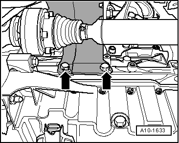
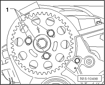
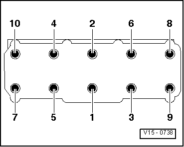
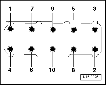
–  Slacken cylinder head bolts in the sequence -1 ... 10-.
–  Swivel cylinder head to the left and out of toothed belt cover (rear).
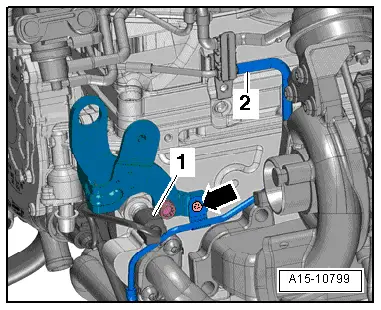
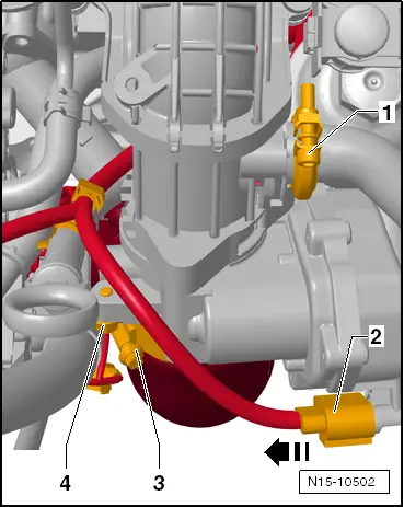
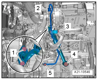
–  Take care not to damage oil return line for turbocharger.
–  Take care to place cylinder head down without bending oil return line. If necessary, place a block of wood below exhaust manifold.
  Caution
Risk of damage to glow plugs when putting down cylinder head.
After removal, the cylinder head must not be put down on the gasket side with the glow plugs still installed, because the glow plugs project slightly beyond the gasket surface.
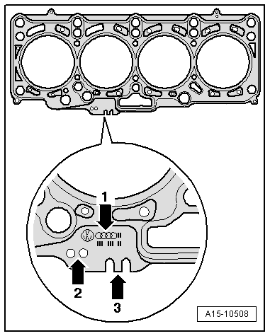
  Note
Audi A1 models with a 1.6 ltr. 4-valve TDI engine (common rail) are always equipped with steel glow plugs.
Installing
Tightening torques
l  → Chapter „Cylinder head - exploded view“.
l  → Chapter „Toothed belt - exploded view“.
  Caution
Avoid damage to sealing surfaces.
t  Carefully remove sealant residue from cylinder head and cylinder block.
t  Ensure that no long scores or scratches are made on the surfaces.
Avoid damage to cylinder block.
No oil or coolant must be allowed to remain in the blind holes for the cylinder head bolts in the cylinder block.
Risk of leaks at cylinder head gasket.
t  Carefully remove any remaining emery and abrasive material.
t  Do not remove new cylinder head gasket from packaging until it is ready to be fitted.
t  Handle the cylinder head gasket very carefully to prevent damage to the silicone coating or the indented area of the gasket.
Avoid damage to open valves.
When installing an exchange cylinder head, the plastic protectors fitted to protect the open valves should not be removed until the cylinder head is ready to be fitted.
Avoid damage to valves and piston crowns after working on valve gear.
Turn the crankshaft carefully at least 2 rotations to ensure that none of the valves make contact when the starter is operated.
  Note
t  Renew the bolts tightened with specified tightening angle.
t  Renew self-locking nuts as well as seals, gaskets and O-rings.
t  Cylinder heads must not be reworked on TDI engines.
t  When installing an exchange cylinder head, the contact surfaces between roller rocker fingers and cams must be oiled.
t  Secure all hose connections with the correct type of hose clips (same as original equipment) → Electronic parts catalogue.
t  After fitting a new cylinder head or cylinder head gasket, change the engine oil and the coolant in the entire cooling system.
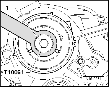
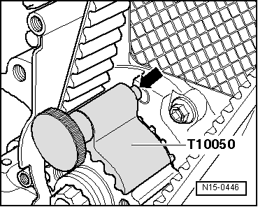
–  Before fitting cylinder head, remove crankshaft stop -T10050- and turn crankshaft against normal direction of rotation until all pistons are positioned approximately equally below „TDC“.
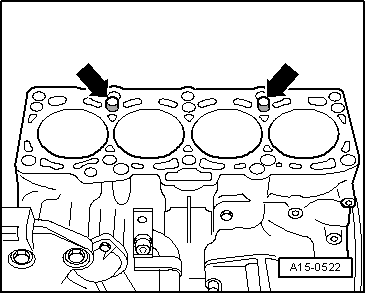
–  If not already fitted, install dowel sleeves in cylinder block for centring cylinder block and cylinder head.
  N15-0026
–  Note cylinder head gasket identification:
1 - Part number
2 - Holes
3 - Ignore
  Note
t  If the cylinder head gasket or cylinder head have been replaced, select the new cylinder head gasket according to the number of holes on the old gasket.
t  If parts of the crankshaft drive have been renewed, the new cylinder head gasket must be selected by measuring the piston projection at „TDC“ → Chapter.
  A15-10508
–  Fit cylinder head gasket onto dowel sleeves -arrows- in cylinder block.
l  Installation position of cylinder head gasket: the word „oben“ (top) or the part number should face towards the cylinder head.
–  Swivel cylinder head so that stud for toothed belt tensioning roller is inserted into aperture in toothed belt cover (rear).
  Note
Make sure that electrical wiring to Hall sender -G40- is properly routed.
–  Fit cylinder head.
–  Screw in cylinder head bolts by hand until they make contact.
  A15-0522
–  Tighten cylinder head bolts → Fig..
  Note
Cylinder head bolts do not have to be torqued down again later after repair work.
–  Install rear toothed belt cover, camshaft hub and sprocket → Chapter.
  V15-0738
–  Lock camshaft hub with diesel injection pump locking pin -3359-.
  Note
Disregard -arrows-.
  A15-10798
–  Lock high-pressure pump hub with diesel injection pump locking pin -3359-.
  Note
Disregard -item 1-.
  A13-10615
–  Then turn crankshaft in direction of engine rotation until pin -arrow- on crankshaft stop -T10050- engages in sealing flange as crankshaft rotates.
–  Install toothed belt (adjust valve timing) → Anchor.
Remaining installation steps are carried out in reverse sequence; note the following:
–  Install cylinder head cover → Chapter.
–  Install heat shield for drive shaft → Anchor.
–  Install support for turbocharger with oil supply line → Chapter.
–  Install exhaust gas recirculation pipes → Chapter.
–  Install particulate filter → Chapter.
–  Install dipstick guide tube → Chapter.
–  Electrical connections and routing → Current flow diagrams, Electrical fault finding and Fitting locations.
–  Install vacuum line to exhaust gas recirculation cooler → Chapter.
–  Install air pipes → Chapter.
–  Install air hoses with screw-type clips → Fig..
–  Install air pipe with connection and pulsation damper → Chapter.
–  Install plenum chamber partition panel → Rep. gr.50.
–  Install air cleaner housing → Rep. gr.23.
–  Change engine oil → Booklet819.
–  Fill cooling system with fresh coolant → Anchor.
  N15-0446

Checking compression > < Cylinder head - exploded view