
A1
| Turbocharger - exploded view |
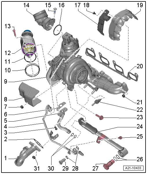
| 1 - | Pipe for exhaust gas recirculation |
| q | With flexible joint; do not bend joint - risk of cracking |
| 2 - | Gasket |
| q | Renew |
| 3 - | Ribbed bolt |
| q | Renew |
| q | 17 Nm |
| 4 - | Oil supply line |
| q | Tighten union nut to 22 Nm |
| 5 - | Oil return line |
| 6 - | Gasket |
| q | Renew |
| 7 - | Nut |
| q | 24 Nm |
| 8 - | Heat shield |
| 9 - | Turbocharger |
| q | Can only be renewed together with exhaust manifold and vacuum unit as one unit |
| q | Removing and installing → Chapter |
| 10 - | Retaining ring |
| q | Can only be installed in one position |
| 11 - | O-ring |
| q | Renew |
| 12 - | Pulsation damper |
| 13 - | Bolt |
| q | 9 Nm |
| 14 - | Intake connecting pipe |
| 15 - | Bolt |
| q | 9 Nm |
| q | Captive in intake connecting pipe |
| 16 - | O-ring |
| q | Renew |
| 17 - | Bracket |
| q | For electrical wiring |
| 18 - | Bolt |
| q | 15 Nm |
| 19 - | Heat shield |
| 20 - | Gasket |
| q | Renew |
| 21 - | Nut |
| q | Renew |
| q | Coat thread with high-temperature paste; for high-temperature paste refer to → Electronic parts catalogue |
| q | 24 Nm |
| 22 - | Exhaust gas temperature sender 1 -G235- |
| q | Removing and installing → Chapter |
| 23 - | Bolt |
| q | 20 Nm |
| 24 - | Support |
| q | For turbocharger |
| 25 - | Bolt |
| q | 9 Nm |
| 26 - | O-rings |
| q | Different diameters |
| q | Renew |
| 27 - | Banjo bolt |
| q | Renew |
| q | 60 Nm |
| 28 - | Seals |
| q | Renew |
| 29 - | Banjo bolt |
| q | 30 Nm |
| 30 - | O-rings |
| q | Renew |
| 31 - | Nut |
| q | 24 Nm |