| t
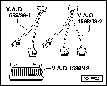
| Adapter cable -V.A.G 1598/39- |
| t
| Test box -V.A.G 1598/42- |

Note | t
| The test box -V.A.G 1598/42- has 105 sockets. It can be connected to the engine control unit via 2 different adapter cables. |
| t
| Each engine control unit is connected to the vehicle's wiring harness via two connectors, one of which has 60 pins, the other has 94 pins. |
| t
| The test box -V.A.G 1598/42- is designed so it can be connected both to the wiring harness for the engine control unit and to the engine control unit itself at the same time. The advantage of this is that the electronic engine control system remains fully functional when the test box is connected (for example, for measuring signals when the engine is running). |
| t
| Always use auxiliary measuring set -V.A.G 1527B- to connect test equipment (e.g. voltage tester -V.A.G 1526D-, hand-held multimeter -V.A.G 1594C- etc.). |
| The engine control unit has to be removed before connectors can be unplugged from engine control unit → Chapter. |

Caution | Electronic components are susceptible to damage. |
| Select the appropriate measuring range before connecting the test leads and observe test requirements. |
|
| –
| Connect test box -V.A.G 1598/42- to wiring harness with adapter cable -V.A.G 1598/39-1- or adapter cable -V.A.G 1598/39-2-. Connect earth clip of test box to negative terminal of battery. The instructions for performing the individual tests indicate whether or not the engine control unit itself also needs to be connected to the test box. |
| –
| Carry out test as described in repair procedure. |
| –
| Make sure you fit protective housing back on engine control unit. |
| –
| Clean threaded holes for shear bolts to remove any residue from locking fluid. This can be done using a thread tap. |
| –
| Always use new shear bolts. |
| –
| Interrogate event memory and erase if necessary. |
|
|
|
