
A1
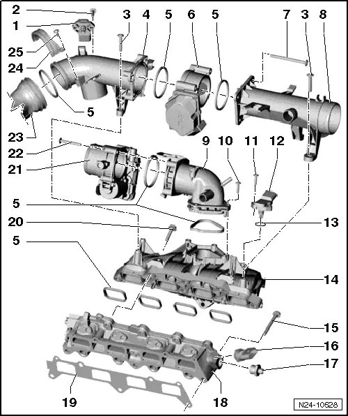
| 1 - | Intake air temperature sender 3 -G520- with intake manifold pressure sender 3 -G583- |
| 2 - | Bolt |
| q | 5 Nm |
| 3 - | Bolt |
| q | Thread-cutting bolt |
| q | 7 Nm |
| 4 - | Intake connecting pipe |
| 5 - | Seal |
| q | Renew |
| 6 - | Regulating flap control unit -J808- with regulating flap potentiometer -G584- |
| q | Removing and installing → Chapter „Removing and installing regulating flap control unit -J808-“ |
| 7 - | Bolt |
| q | Thread-cutting bolt |
| q | 7 Nm |
| 8 - | Intake connecting pipe |
| 9 - | Intake manifold connection |
| 10 - | Bolt |
| q | Thread-cutting bolt |
| q | 7 Nm |
| 11 - | Bolt |
| q | 5 Nm |
| 12 - | Intake manifold pressure sender -G71- |
| 13 - | O-ring |
| q | Renew |
| 14 - | Intake manifold |
 Note
Note| t | If intake manifold has been removed, check that all hoses are securely seated at the intake manifold after installation. |
| t | Check that hoses with fasteners are engaged securely by pulling at them. |
| q | Regulating flap control unit -J808- and throttle valve module -J338- must be removed before intake manifold can be removed |
| q | Removing and installing → Chapter |
| 15 - | Bolt |
| q | 20 Nm |
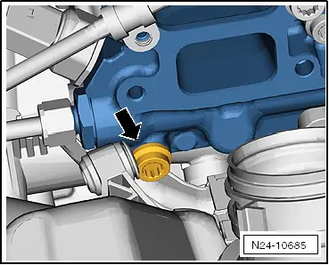
| 16 - | Fuel pressure sender -G247- |
| q | 22 Nm |
| q | Removing and installing → Chapter |
| 17 - | Connection |
| q | 80 Nm |
| 18 - | Intake manifold (bottom section) |
| q | Regulating flap control unit -J808-, throttle valve module -J338- and intake manifold must be removed before intake manifold (bottom section) can be removed → Chapter „Removing and installing intake manifold (bottom section) with fuel rail“ |
| 19 - | Gasket |
| q | Renew |
| q | Note installation position |
| 20 - | Bolt |
| q | 20 Nm |
| 21 - | Throttle valve module -J338- |
| q | Removing and installing → Chapter „Removing and installing throttle valve module -J338-“ |
| q | Cleaning → Chapter |
| q | After this component has been renewed, learnt values must be erased and engine control unit -J623- must be adapted using → Vehicle diagnostic tester |
| 22 - | Bolt |
| q | 7 Nm |
| 23 - | Pressure pipe |
| q | From turbocharger |
| 24 - | Retaining clip |
| 25 - | Bolt |
| q | 7 Nm |
Note
|
|