
A1
| Overview of fitting locations |
| Engine compartment |
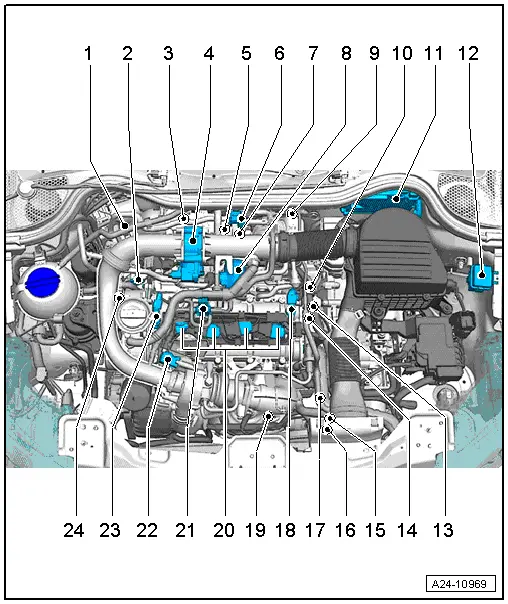
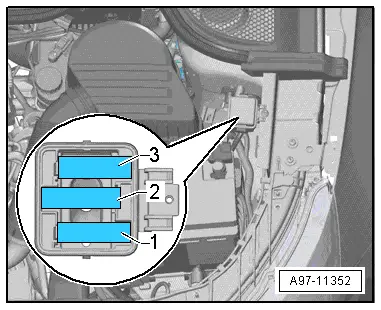
| 1 - | Intake air temperature sender 3 -G520- with intake manifold pressure sender 3 -G583- |
| 2 - | Charge pressure sender -G31- / intake air temperature sender 2 -G299- |
| q | Fitting location → Fig. |
| q | Removing and installing → Rep. gr.21 |
| 3 - | Throttle valve module -J338- |
| q | Including throttle valve drive for electric throttle -G186-, throttle valve drive angle sender 1 for electric throttle -G187- and throttle valve drive angle sender 2 for electric throttle -G188- |
| q | Removing and installing → Chapter |
| 4 - | Regulating flap control unit -J808- |
| q | With regulating flap potentiometer -G584- |
| q | Removing and installing → Chapter |
| 5 - | Knock sensor 1 -G61- |
| q | Exploded view → Chapter |
| q | Removing and installing → Chapter |
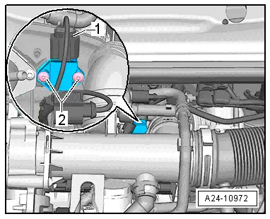
| 6 - | Activated charcoal filter solenoid valve 1 -N80- |
| q | Fitting location → Fig. |
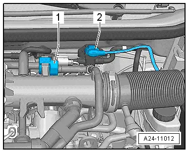
| 7 - | Intake manifold pressure sender -G71- with intake air temperature sender -G42- |
| q | Fitting location |
| 8 - | High-pressure pump |
| q | With fuel pressure regulating valve -N276- |
| q | Removing and installing → Fig. |
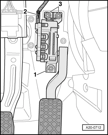
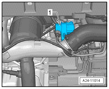
| 9 - | Brake servo pressure sensor -G294- |
| q | Fitting location → Fig. |
| 10 - | Fuel pressure sender -G247- |
| q | Exploded view → Chapter |
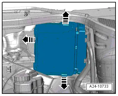
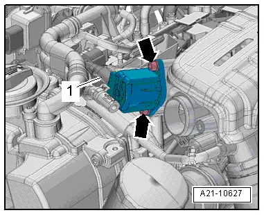
| 11 - | Engine control unit -J623- |
| q | Fitting location → Fig. |
| 12 - | Additional coolant pump relay -J496- |
| q | Fitting location → Fig. |
| 13 - | Coolant temperature sender -G62- |
| q | Fitting location → Fig. |
| q | Removing and installing → Rep. gr.19 |
| 14 - | Oil pressure switch -F1- |
| q | Fitting location → Fig. |
| q | Removing and installing → Rep. gr.17 |
| 15 - | Radiator fan control unit -J293- |
| q | Removing and installing → Rep. gr.19 |
| 16 - | Radiator outlet coolant temperature sender -G83- |
| q | Fitting location → Fig. |
| q | Removing and installing → Rep. gr.19 |
| 17 - | Coolant circulation pump -V50- |
| q | Fitting location → Fig. |
| q | Removing and installing → Rep. gr.19 |
| 18 - | Hall sender -G40- |
| q | Exploded view → Chapter |
| q | Removing and installing → Chapter |
| 19 - | Lambda probes |
| q | Removing and installing Lambda probe -G39- with Lambda probe heater -Z19- → Chapter |
| q | Removing and installing Lambda probe after catalytic converter -G130- with Lambda probe 1 heater after catalytic converter -Z29- → Chapter |
| q | Fitting location → Fig. |
| q | Exploded view → Chapter |
| 20 - | Ignition coils and injectors |
| q | Ignition coil 1 with output stage -N70- |
| q | Ignition coil 2 with output stage -N127- |
| q | Ignition coil 3 with output stage -N291- |
| q | Ignition coil 4 with output stage -N292- |
| q | Injector, cylinder 1 -N30- |
| q | Injector, cylinder 2 -N31- |
| q | Injector, cylinder 3 -N32- |
| q | Injector, cylinder 4 -N33- |
| q | Exploded view → Chapter |
| 21 - | Charge pressure control solenoid valve -N75- |
| 22 - | Turbocharger air recirculation valve -N249- |
| q | Fitting location → Fig. |
| q | Removing and installing → Rep. gr.21 |
| 23 - | Camshaft control valve 1 -N205- |
| q | Removing and installing → Rep. gr.15 |
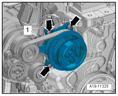
| 24 - | Magnetic clutch for supercharger -N421- |
| q | Combined with coolant pump in one unit |
| q | Fitting location → Fig. |
| q | Removing and installing → Rep. gr.19 |
| Engine (intake side) |
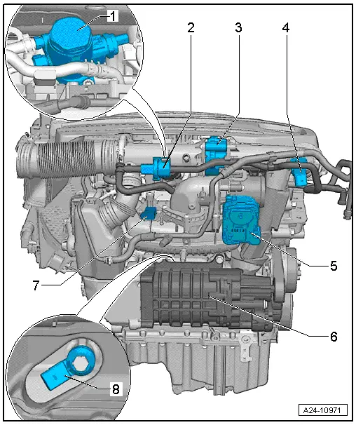
| 1 - | High-pressure pump |
| q | With fuel pressure regulating valve -N276- |
| q | Removing and installing → Chapter |
| 2 - | Activated charcoal filter solenoid valve 1 -N80- |
| 3 - | Regulating flap control unit -J808- |
| q | With regulating flap potentiometer -G584- |
| q | Removing and installing → Chapter |
| 4 - | Throttle valve module -J338- |
| q | Including throttle valve drive for electric throttle -G186-, throttle valve drive angle sender 1 for electric throttle -G187- and throttle valve drive angle sender 2 for electric throttle -G188- |
| q | Removing and installing → Chapter |
| 5 - | Intake air temperature sender 3 -G520- with intake manifold pressure sender 3 -G583- |
| 6 - | Supercharger |
| q | Removing and installing → Rep. gr.21 |
| 7 - | Intake manifold pressure sender -G71- with intake air temperature sender -G42- |
| 8 - | Knock sensor 1 -G61- |
| q | Exploded view → Chapter |
| q | Removing and installing → Chapter |
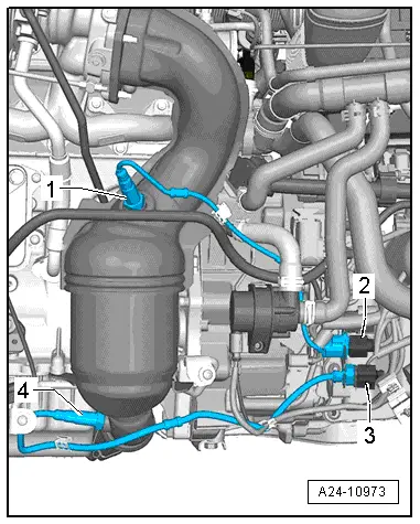
| Engine (gearbox end) |
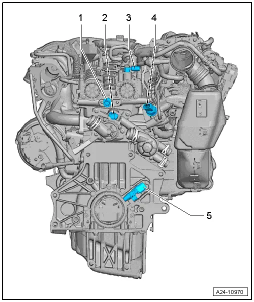
| 1 - | Oil pressure switch -F1- |
| q | Fitting location → Fig. |
| q | Removing, installing and checking → Rep. gr.17 |
| 2 - | Coolant temperature sender -G62- |
| q | Fitting location → Fig. |
| q | Removing and installing → Rep. gr.19 |
| 3 - | Hall sender -G40- |
| q | Removing and installing → Chapter |
| 4 - | Fuel pressure sender -G247- |
| q | Exploded view → Chapter |
| 5 - | Engine speed sender -G28- |
| q | Exploded view → Chapter |
|
|
 Note
Note
|
|
|
|
|
|
|
|
|
|
|

|
|
|
|
|
|
|
|
|
|
|
|
|