
A1
| Overview of fitting locations |
| Engine compartment |

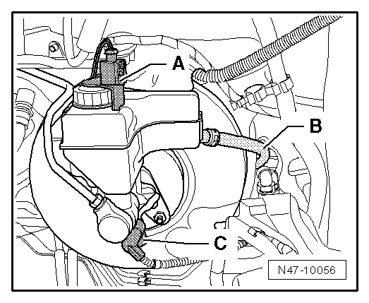
| 1 - | Brake vacuum pump -V192- |
| 2 - | Camshaft control valve 1 -N205- |
| q | Removing and installing → Rep. gr.15 |
| 3 - | Injector, cylinder 1 -N30- |
| q | Exploded view → Chapter |
| 4 - | Injector, cylinder 2 -N31- |
| q | Exploded view → Chapter |
| 5 - | Injector, cylinder 3 -N32- |
| q | Exploded view → Chapter |
| 6 - | Injector, cylinder 4 -N33- |
| q | Exploded view → Chapter |
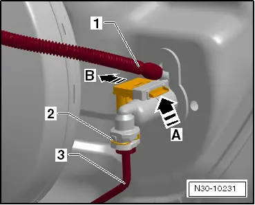
| 7 - | Brake servo pressure sensor -G294- |
| q | Fitting location → Fig. |
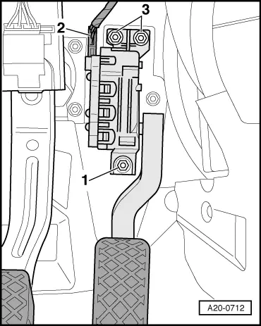
| 8 - | Brake light switch - F-/brake pedal switch -F63- |
| q | Fitting location → Fig. |
| q | Removing and installing → Rep. gr.45 |
| 9 - | Accelerator position sender -G79- and accelerator position sender 2 -G185- |
| q | Fitting location → Fig. |
| 10 - | Clutch position sender -G476- |
| q | For vehicles with manual gearbox |
| q | Fitting location → Fig. |
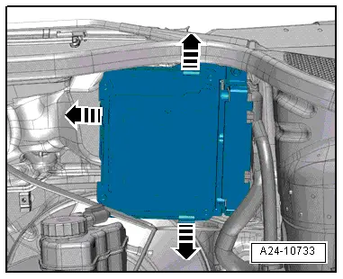
| 11 - | Engine control unit -J623- |
| q | Fitting location → Fig. |
| 12 - | Hall sender -G40- |
| q | Camshaft position sensor |
| q | Exploded view → Chapter |
| 13 - | Gearbox neutral position sender -G701- |
| q | For vehicles with manual gearbox |
| q | Fitting location → Fig. |
| 14 - | Turbocharger air recirculation valve -N249- |
| q | Removing and installing → Rep. gr.21 |
| 15 - | Lambda probe after catalytic converter -G130- with Lambda probe 1 heater after catalytic converter -Z29- |
| q | Exploded view → Chapter |
| 16 - | Lambda probe -G39- with Lambda probe heater -Z19- |
| q | Exploded view → Chapter |
| 17 - | Ignition coil 4 with output stage -N292- |
| q | Exploded view → Chapter |
| 18 - | Ignition coil 3 with output stage -N291- |
| q | Exploded view → Chapter |
| 19 - | Ignition coil 2 with output stage -N127- |
| q | Exploded view → Chapter |
| 20 - | Ignition coil 1 with output stage -N70- |
| q | Exploded view → Chapter |
| Engine (intake side) |
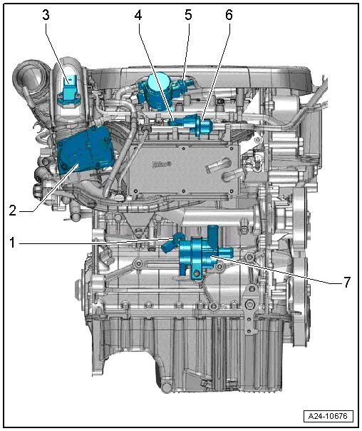
| 1 - | Knock sensor 1 -G61- |
| q | Exploded view → Chapter |
| q | Removing and installing → Chapter |
| 2 - | Throttle valve module -J338- |
| q | Including throttle valve drive for electric throttle -G186-, throttle valve drive angle sender 1 for electric throttle -G187- and throttle valve drive angle sender 2 for electric throttle -G188- |
| q | After throttle valve module -J338- or engine control unit has been renewed, throttle valve module must be re-adapted to engine control unit -J623- using → Vehicle diagnostic tester |
| q | Exploded view → Chapter |
| 3 - | Charge pressure sender -G31- / intake air temperature sender 2 -G299- |
| q | Removing and installing → Rep. gr.21 |
| 4 - | Intake air temperature sender -G42- / intake manifold pressure sender -G71- |
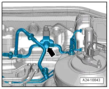
| 5 - | Fuel pressure regulating valve -N276- |
| 6 - | Activated charcoal filter solenoid valve 1 -N80- |
| 7 - | Coolant circulation pump -V50- |
| q | Removing and installing → Rep. gr.19 |
| Engine (gearbox end) |
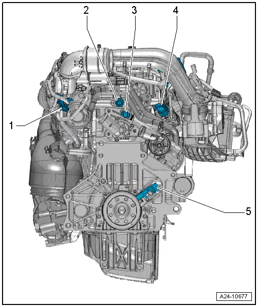
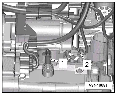
| 1 - | Charge pressure control solenoid valve -N75- |
| 2 - | Oil pressure switch -F1- |
| q | Removing, installing and checking → Rep. gr.17 |
| 3 - | Coolant temperature sender -G62- |
| q | Removing and installing → Rep. gr.19 |
| 4 - | Fuel pressure sender -G247- |
| q | Exploded view → Chapter |
| 5 - | Engine speed sender -G28- |
| q | Exploded view → Chapter |
|
|
 Note
Note
|
|
|
|
|
|
Note
|
|
|
|