audi Workshop Repair Guides

Audi Workshop Service and Repair Manuals

Ignition system, glow plug system > < Wiring and component check with test boxV.A.G 1598/42
Removing and installing engine control unitJ623
Removing and installing engine control unit -J623-
  Note
t  Not every engine control unit is bolted to a protective housing. Whether a protective housing is fitted depends on the engine/gearbox combination.
   
t  The engine control unit -1- is bolted to the protective housing -5-. To make it more difficult to unscrew the shear bolts -4- for locking plate -2-, their threads have been coated with locking fluid.
t  The protective housing has to be removed before the connectors can be unplugged from the engine control unit (e.g. to connect the test box or renew the engine control unit).
Special tools and workshop equipment required
  A24-0593
t  Hot air blower -VAS 1978/14A--item 1- with nozzle attachment -2- from wiring harness repair set -VAS 1978 B-
t  Small mole grips -3- (commercially available)
Removing
–  Before removing the engine control unit -J623-, the adaption values of the injectors and the ash deposit mass must be read out. Use → Vehicle diagnostic tester.
–  Store adaption values as electronic file.
–  Switch off ignition and take out ignition key.
–  Remove air cleaner housing → Chapter.
  A24-0475
–  Release fasteners -arrows- and detach engine control unit -J623- from bracket.
  Note
  A24-10733
t  The threads of the two shear bolts -4- which are not screwed into the engine control unit -1- are secured with locking fluid. To unscrew these two bolts, the threads must therefore be heated with the hot air blower.
t  The threads of the two shear bolts -3- which are screwed into the engine control unit are not secured with locking fluid. Do not apply heat to the threads in the control unit housing; this is not necessary and would cause overheating of the control unit.
  A24-0593
  Caution
Wiring, connectors, insulation and control units can be burnt and damaged.
Keep exactly to the following procedure. Observe operating instructions for hot air blower.
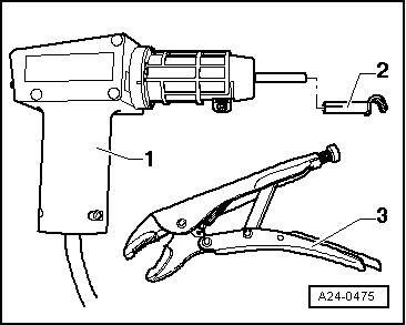
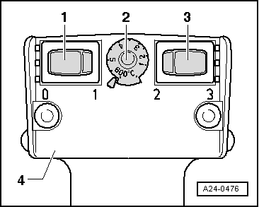
–  Select settings on hot air blower -4- as shown in illustration:
2 - Temperature potentiometer to maximum heat output
3 - Two-stage air flow switch to position „3“
  Note
t  
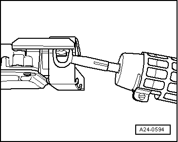
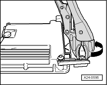
Then use hot air blower to heat threaded holes in protective housing into which shear bolts have been screwed. This reduces the inhibiting action of the locking fluid on the shear bolt threads and makes it easier to unscrew these bolts.
t  Cover up all painted parts to avoid any damage caused by hot air blower or vice-grip pliers.
  WARNING
Risk of burns.
Parts of the protective housing will become very hot as a result of heating the shear bolts. Try to ensure that only the thread is heated and none of the nearby components. These should be covered if necessary.
  A24-0476
Switch on the hot air blower and heat the bolt for approximately 20 ... 30 seconds.
  A24-0594
–  Then grasp bolt head with vice-grip pliers and unscrew shear bolt.
–  The two shear bolts screwed into the engine control unit do not need to be heated. They can be removed without heating.
–  Detach protective housing from control unit connectors.
–  Release connectors on engine control unit -J623- and unplug connectors.
Installing
Installation is carried out in the reverse order; note the following:
–  After installation, the protective housing must be re-fitted on the engine control unit -J623-.
–  Clean threaded holes for shear bolts to remove any residue from locking fluid. This can be done using a thread tap.
–  Always use new shear bolts.
–  Install air cleaner housing → Chapter.
The procedure required after connecting the new engine control unit is described in the Guided Fault Finding or Guided Functions. Use → Vehicle diagnostic tester.
  A24-0595

Ignition system, glow plug system > < Wiring and component check with test boxV.A.G 1598/42