audi Workshop Repair Guides

Audi Workshop Service and Repair Manuals

Shock absorbers, coil springs > < Removing and installing axle beam
Renewing bonded rubber bushes
   
Renewing bonded rubber bushes
Special tools and workshop equipment required
t  Thrust piece -3416/2-
t  Assembly tool -T10205-
t  Assembly tool -T10254-
t  Assembly tool -T10263-
t  Torque wrench -V.A.G 1332-
t  Thrust piece -3348/1- from assembly tool -3348-
t  Two hose clips from charge air system tester -V.A.G 1687-

  W00-0308
t  Engine and gearbox jack -V.A.G 1383 A- with universal gearbox support -V.A.G 1359/2-
t  Hydraulic press -VAS 6178-
t  Foot pump -VAS 6179-
t  Ring spanner insert -V.A.G 1332/10-

Removing
–  Release handbrake.
  W00-0953
–  Before commencing work, use measuring tape or similar to measure dimension -a- from wheel centre to lower edge of wheel housing.
l  This measurement must be taken with the suspension in the unladen position (vehicle unladen).
–  Make a note of the measured value. This will be needed when tightening the bolts and/or nuts on the suspension.
–  Raise vehicle to working height.
–  Remove wheels.
–  Remove wheel spoiler on both sides → Rep. gr.66.
  A42-10125
–  Unclip wire -2- for speed sensor from brackets -arrows- on both sides.
  A42-10448
Vehicles with dynamic headlight range control
–  Remove bolts -1 and 3-. Vehicle level sender -G76- with bracket -2- does not have to be removed.
  A42-10449
All vehicles (continued):
–  Remove clip -arrow B- for brake line (right-side).
–  Pull brake hose (right-side) -1- out of bracket.
  A42-10426
–  Unclip ABS wire (right-side) at bracket -1- and move clear.
  A42-10455
–  Remove handbrake cables from retainers on both sides -arrows-.
–  Bring engine and gearbox jack -V.A.G 1383 A- into position with a suitable support block or similar.
–  Secure rear axle with a strap or similar when lowering.
–  Unscrew bolts -1- for axle beam on both sides.
–  Carefully lower rear axle with engine and gearbox jack -V.A.G 1383 A- until bonded rubber bush is accessible.
  Note
When lowering the rear axle take care not to damage or kink the brake lines on either side.
  A42-10428
–  Mark installation position of bonded rubber bush -1- in relation to axle beam at bottom slit in outer sleeve -arrow- using a felt-tip pen or similar
–  Extend marking to opposite side of sleeve.
  A42-10450
–  Set up special tools as shown in illustration.
1 - Spindle -T10254/5-
2 - Nut -T10254/4-
3 - Thrust piece -3416/2-
4 - Bonded rubber bush
5 - Tube -T10263/6-
6 - Thrust plate -T10205/1-
7 - Foot pump -VAS 6179-
8 - Hydraulic press -VAS 6178- with press attachment -T10205/13-
9 - Nut -T10254/4-
–  Take up play in special tools.
  A42-10451
–  Tube -T10263/6--1- must be positioned on bonded rubber bush so that outer diameter is able to rest evenly on axle beam -arrow-.
–  Pull out bonded rubber bush by operating the pump.
  Note
The outer ring of the bonded rubber bush will shear off with a loud bang when the bush is removed.
  A42-10430
–  The bonded rubber bush must be removed from the tube -T10356/6- once the bush has been pulled out.
–  Clamp the tube -T10356/6- in a vice at the surfaces provided for this purpose.
–  Use a screwdriver as a lever -arrow- between tube -T10356/6- and rubber bonded bush; if necessary, knock bonded rubber bush out by tapping a drift gently with a hammer.
  N42-10321
Installing
l  The outer sleeve of the bonded rubber bush consists of two half-sections which have to be pressed together before installation in order to press the bush into the axle beam without damage.
–  Compress new bonded rubber bush -1- with two hose clips -arrows- as shown in illustration until the two half-sections come together.
  A42-10452
–  Now bring bonded rubber bush with special tools into position at rear axle.
1 - Spindle -T10254/5-
2 - Nut -T10254/4-
3 - Hydraulic press -VAS 6178- with press attachment -T10205/13-
4 - Foot pump -VAS 6179-
5 - Thrust plate -T10205/1-
6 - Tube -T10263/6-
7 - Bonded rubber bush
8 - Thrust piece -3348/1-
9 - Nut -T10254/4-
  A42-10453
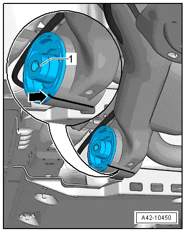
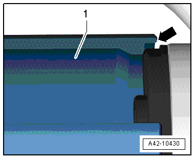
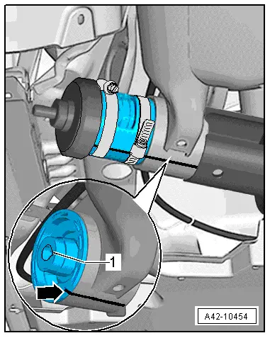
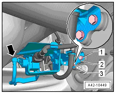
–  Before pressing in bonded rubber bush, make sure groove -1- in inner core of bush faces towards rear of vehicle and bottom slit -arrow- in outer sleeve is in line with marking on axle beam.
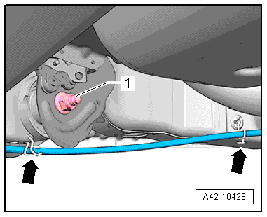
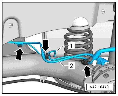
–  Press in bonded rubber bush as far as first hose clip and then remove hose clip.
–  Press in bonded rubber bush as far as second hose clip and then remove hose clip.
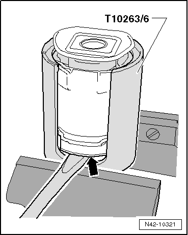
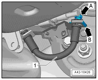
–  Press in bonded rubber bush as far as stop.
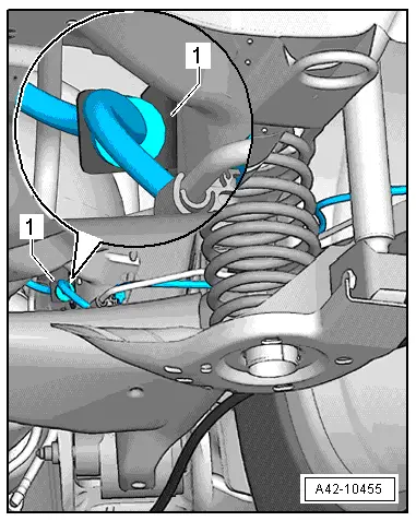
–  After installation, check that bonded rubber bush is in correct position.
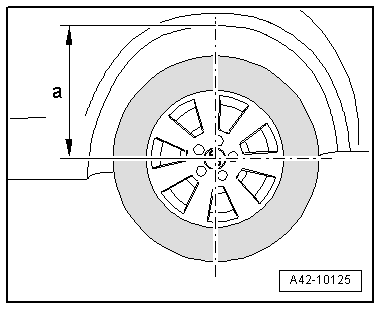
–  Tighten rear axle mountings in unladen position → Chapter.
Remaining installation steps are carried out in reverse sequence.
Tightening torque → Chapter „Exploded view - axle beam with attachments“
  A42-10454

Shock absorbers, coil springs > < Removing and installing axle beam