Audi Workshop Service and Repair Manuals
HOME
FEATURES
MENU
INDEX
ABOUT US
Pin assignment of MMI Navigation system plus >
< MMI Navigation system plus - layout
A1
Vehicle electrics
Communication / Infotainment
Navigation system
Pin assignment for Ready4Nav
Pin assignment for Ready4Nav
Pin assignment for Ready4Nav
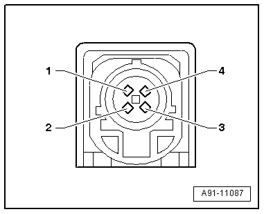
Control unit 1 for information electronics -J794-
1 -
Connection (AM/FM1) from aerial amplifier -R24- on normal roof / aerial amplifier 2 -R111- with roof spoiler (radio aerial 2 -R93-)
2 -
Connection (DAB) from aerial amplifier 3 -R112- (digital radio aerial -R183-)
3 -
GPS connection from GPS aerial -R50-
4 -
Connection block with four multi-pin connectors
5 -
MOST bus
6 -
Multi-pin connector, 4-pin (T4ap) to connection for external audio sources -R199-/internet access control unit -J666-
7 -
Multi-pin connector, 4-pin (T4al) to display unit for front information display and operating unit control unit -J685-
8 -
Connection (FM2) from aerial amplifier -R24- (aerial -R11-)
Note
Contacts which are not listed are not used.
4 - Connection block with four multi-pin connectors
A - Multi-pin connector, 8-pin (T8ag)
1 -
Loudspeaker (+), rear right
2 -
Loudspeaker (+), front right
3 -
Loudspeaker (+), front left
4 -
Loudspeaker (+), rear left
5 -
Loudspeaker (–), rear right
6 -
Loudspeaker (–), front right
7 -
Loudspeaker (–), front left
8 -
Loudspeaker (–), rear left
B - Multi-pin connector, 12-pin (T12)
4 -
Microphone input (+) from microphone unit in front roof module -R164- (telephone microphone -R38-)
6 -
DIAG signal from telephone bracket -R126-
12 -
Microphone input (–) from microphone unit in front roof module -R164- (telephone microphone -R38-)
C - Multi-pin connector, 12-pin (T12y)
All pins are connected to the connection for external audio sources -R199-.
1 -
NF in, earth (low frequency)
2 -
NF in, right-side (low frequency)
3 -
USB (+5 V) - not with internet access control unit -J666-
4 -
USB (earth)
5 -
iPod (ACC power)
6 -
Detect - not with internet access control unit -J666-
7 -
NF in, left-side (low frequency)
8 -
NF in, screen earth (low frequency)
9 -
FBAS wire (+)
10 -
FBAS wire (–)
11 -
iPod data
12 -
iPod data
The following pins are also connected to the internet access control unit -J666-.
3 -
USB (+5 V)
4 -
USB (earth)
6 -
Detect
D - Multi-pin connector, 8-pin (T10ag)
9 -
Subwoofer -R211-
10 -
Centre loudspeaker -R208-
13 -
Subwoofer -R211-
14 -
Centre loudspeaker -R208-
17 -
Terminal 31
18 -
Terminal 30
E - Multi-pin connector, 12-pin (T12w)
7 -
Open circuit diagnostic lead
12 -
Switch-on signal for telephone bracket -R126-/aerial amplifier for mobile telephone -R86-
5 - MOST bus
1 -
Input
2 -
Output
6 - Multi-pin connector, 4-pin (T4ap)
All pins are connected to the connection for external audio sources -R199-/internet access control unit. -J666-.
1 -
D (+)
2 -
iPod detected
3 -
D (–)
4 -
Earth
7 - Multi-pin connector, 4-pin (T4al)
All pins are connected to the display unit for front information display and operating unit control unit -J685-.
1 -
LVDS (–)
2 -
LIN
3 -
LVDS (+)
4 -
Earth
Vehicle electrics
Communication / Infotainment
Navigation system
Pin assignment for Ready4Nav
Pin assignment of MMI Navigation system plus >
< MMI Navigation system plus - layout
 Note
Note


 Note
Note