Vehicle electricsPin assignment on radio chorus
| Pin assignment on radio chorus |
|
|
|
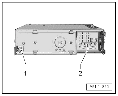
| 1 - | Connection (AM/FM1) from roof aerial -R216- (aerial -R11-) |
| 2 - | Connection block with four multi-pin connectors |

Note | Contacts which are not listed are not used. |
| 2 - Connection block with four multi-pin connectors |
|
|
|
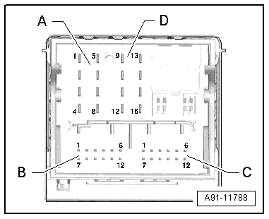
| A - Multi-pin connector, 8-pin (T8d) |
| 1 - | Loudspeaker (+), rear right |
| 2 - | Loudspeaker (+), front right |
| 3 - | Loudspeaker (+), front left |
| 4 - | Loudspeaker (+), rear left |
| 5 - | Loudspeaker (–), rear right |
| 6 - | Loudspeaker (–), front right |
| 7 - | Loudspeaker (–), front left |
| 8 - | Loudspeaker (–), rear left |
|
|
|
| C - Multi-pin connector, 12-pin (T12) |
| 6 - | NF (–) (low frequency) from pre-fitted components for mobile phone installation |
| 10 - | NF mute (low frequency) from pre-fitted components for mobile phone installation |
| 12 - | NF (+) (low frequency) from pre-fitted components for mobile phone installation |
|
|
|
| D - Multi-pin connector, 8-pin (T8e) |
| 9 - | CAN bus High (Infotainment) |
| 10 - | CAN Bus Low (Infotainment) |
| 16 - | Permanent live connected to PIN 15 (anti-theft alarm) |
|
|
|
05 General