audi Workshop Repair Guides

Audi Workshop Service and Repair Manuals

Pin assignment of multi-pin connector on data bus diagnostic interfaceJ533 - with fibre optic cable > < Removing and installing data bus diagnostic interfaceJ533
Pin assignment of multi-pin connector on data bus diagnostic interfaceJ533 - without fibre optic cable
Pin assignment of multi-pin connector on data bus diagnostic interface -J533- - without fibre optic cable
   
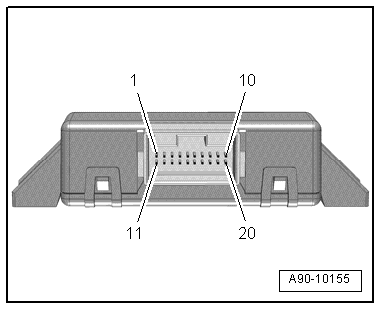
Multi-pin connector, 20-pin
1 - Battery + (terminal 30)
2 - LIN data bus 1
3 - Not used
4 - Not used
5 - CAN bus Low (convenience)
6 - CAN bus Low (drive)
7 - Not used
8 - CAN bus Low (instrument cluster)
9 - CAN Bus Low (diagnosis)
10 - Ring circuit break diagnostic lead
11 - Earth – (terminal 31)
12 - LIN data bus 2
13 - Instrument cluster wake-up
14 - Terminal 15
15 - CAN bus High (convenience)
16 - CAN bus High (drive)
17 - CAN bus High (extended)
18 - CAN bus High (instrument cluster)
19 - CAN bus High (diagnosis)
20 - Not used
  A90-10155

Pin assignment of multi-pin connector on data bus diagnostic interfaceJ533 - with fibre optic cable > < Removing and installing data bus diagnostic interfaceJ533