| –
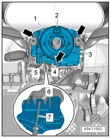
| Apply screwdriver -7- at retaining hook -6-, as shown in illustration, and carefully release electrical connectors -1, 3, 4, 5-. |
| –
| Detach steering column electronics control unit -J527--item 2- from steering column switch module. |
| Installation is carried out in the reverse order; note the following: |
| –
| Make sure all electrical connectors are properly engaged. |
| –
| Install trim panels for steering column switch module → Rep. gr.68. |
| –
| After renewing return ring with slip ring, perform calibration of steering angle sender -G85- in „Guided Fault Finding“ or „Guided Functions“ mode → Vehicle diagnostic tester. |
|
|
|
 Note
Note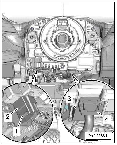
 WARNING