
A2
| → Indicated on display: |
|
||
|
Note: Address word 00 is used to start the automatic test sequence i.e. interrogation of fault memories of all vehicle systems with self-diagnosis capability in "Rapid data transfer" mode. If a control unit answers with its identification, the number of faults stored or "No fault detected" appears on the display. Any system faults stored will be displayed in sequence and printed out. The V.A.G 1551 will then transmit the next address word. |
 |
|||||||||
|
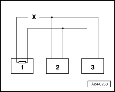
Example 1: The faults stored in the fault memories indicate that control unit 1 does not communicate with control units 2 and 3.
=> "Current Flow Diagrams, Electrical Fault-finding and Fitting Locations" binder
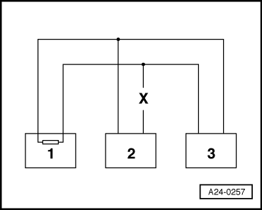
Example 2: |
 |
|||||||||
|
The faults stored in the fault memories indicate that control unit 2 does not communicate with control units 1 and 3.
=> "Current Flow Diagrams, Electrical Fault-finding and Fitting Locations" binder
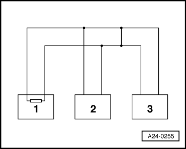
Example 3: With the faults stored in the fault memories it can be seen that there is no sending or receiving operation possible in any of the control units. |
 |
|||||||||
|
 |
|
|
=> "Current Flow Diagrams, Electrical Fault-finding and Fitting Locations" binder
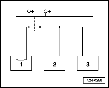
If the causes of the fault, e.g. "Group convenience data bus defective" cannot be found in bus wires, check whether one of the control units is responsible for the fault. All the control units that communicate via the CAN data bus are still disconnected. Ignition is switched off.
|