audi Workshop Repair Guides

Audi Workshop Service and Repair Manuals

Removing and installing components of the ABS/ESP system, ITT Mark 60 > < Removing and installing components of ABS system on rear axle, disk brakes
Brake System
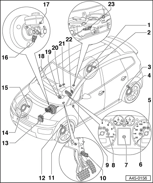
Component overview, ABS/ESP Mark 60
 
A45-0156
  • Rotor for speed sensor, rear right
    • ◆ Rotor is welded to wheel hub. Removing and installing

=> Running Gear, FWD; Repair group 42;

  • Rear right speed sensor -G44
    • ◆ Removing and installing=>Page 45-52
  • Rear left speed sensor -G46
    • ◆ Removing and installing=>Page 45-52
  • Rotor for speed sensor, rear left
    • ◆ Rotor is welded to wheel hub. Removing and installing

=> Running Gear, FWD; Repair group 42;

  • Handbrake warning lamp -K14
    • ◆ Fitting location: in dash panel insert
 
A45-0156
  • ABS warning lamp -K47
    • ◆ Fitting location: in dash panel insert
  • Brake warning symbol -K118
    • ◆ Fitting location: in the dash panel insert in the driver information system
  • TCS/ESP warning lamp -K86
    • ◆ Fitting location: in dash panel insert
  • Relay J508 for brake light suppression
    • ◆ Fitting location: on fuse box
  • Brake light switch -F
    • ◆ The brake light switch is open in the rest position;
    • ‒ Removing and installing the brake light switch =>Page 45-86
 
A45-0156
  • Rotor for speed sensor, front left
    • ◆ Rotor is welded to wheel hub. Removing and installing

=> Running Gear, FWD; Repair group 40;

  • Front left speed sensor -G47
    • ◆ Removing and installing=>Page 45-43
  • Hydraulic control unit -N55 with control unit -J104
    • ◆ The hydraulic pump -V64, the hydraulic unit -N55 and the control unit -J104 form the hydraulic control unit.
    • ◆ Removing and installing=>Page 45-97
  • Rotor for speed sensor, front right
    • ◆ Rotor is welded to wheel hub. Removing and installing

=> Running Gear, FWD; Repair group 40;

 
A45-0156
  • Front right speed sensor -G45
    • ◆ Removing and installing=>Page 45-43
  • Sender G201 for brake pressure -1-
    • ◆ Removing and installing=>Page 45-84
  • Warning contact for brake fluid level F34
  • Lateral acceleration sender -G200
    • ◆ Removing and installing=>Page 45-72
    • ◆ Integrated in the ESP sensor unit -G419 from approx. 09.01 => Fig.1
 
A45-0156
  • Yaw rate sender G202
    • ◆ Removing and installing=>Page 45-72
    • ◆ Integrated in the ESP sensor unit -G419 from approx. 09.01 => Fig.1
  • Switch for TCS/ESP E256
    • ◆ Fitting location: on the centre console
  • Switch for TCS/ESP E256
    • ◆ From approx. 09.01 => Fig.1
    • ◆ Removing and installing=>Page 45-77
  • Steering angle sender G85
    • ◆ Removing and installing=>Page 45-79
  • Handbrake warning switch F9
    • ◆ Fitting location: on the handbrake lever assembly
 
A45-0155

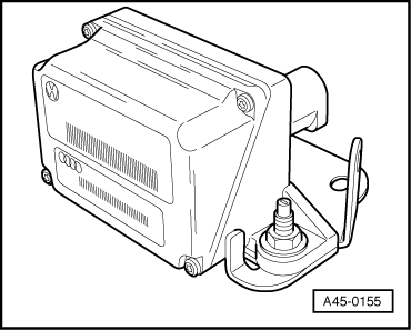
→ Fig.1    ESP sensor unit -G419 from approx. 09.01

The ESP sensor unit comprises the following senders:

  • ◆ Lateral acceleration sender -G200
  • ◆ Yaw rate sender -G202

Removing and installing components of the ABS/ESP system, ITT Mark 60 > < Removing and installing components of ABS system on rear axle, disk brakes