
A2
|
Hydraulic unit, brake servo/brake master cylinder - 1.4 petrol engine and 1.4 TDI engine
Removing and installing control unit and hydraulic unit
|
 |
|
|
→ Sealing plug, repair kit After detaching the control unit from the hydraulic unit, the transport protection for valve domes must always be fitted onto the hydraulic unit. No warranty can be accepted for hydraulic units without transport protection for valve domes.
Removing
|
 |
|
Note:
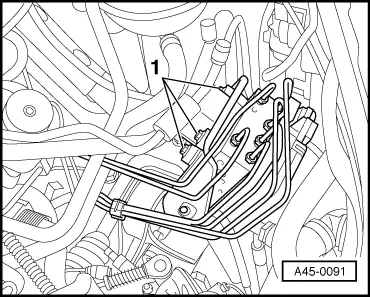
The brake lines in the vicinity of the hydraulic unit must not be bent. |
|
|
|
Note:
Fuel system is pressurised. Place a lint-free cloth around the connection point before opening the system. Then release pressure by carefully loosening the connection.
Ensure that no brake fluid spills onto the contacts. |
 |
|
|
 |
|
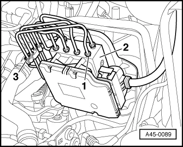
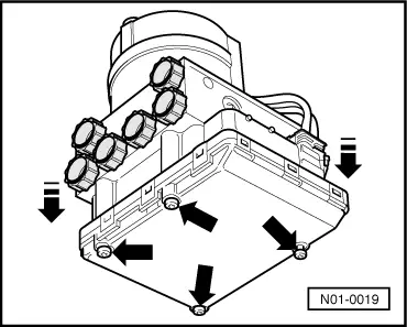
Detaching control unit from hydraulic unit |
 |
|
|
 |
|||||||||||||
|
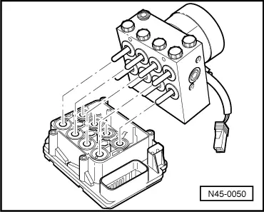
→ When detaching the control unit, ensure that the valve domes of the hydraulic unit are not misaligned by the control unit solenoids. Cover control unit solenoids with a lint free cloth. After separating the control unit from the hydraulic unit, use the transportation protection for the valve domes. Installing
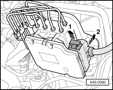
When attaching the control unit to the hydraulic unit, ensure that the valve domes of the hydraulic unit are not misaligned by the control unit solenoids.
Do not fully tighten bolts. Connection of the various brake lines to the hydraulic unit is facilitated thereby.
|