-
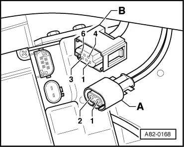
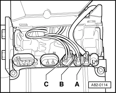
‒ → Detach connectors -A- and -B- from the heater unit.
List of electrical tests
|
|
|---|
|
Test step
|
Component tested
|
Page
|
|
1
|
Power supply and earth connection
To additional heater
|
01-109
|
|
2
|
Actuation of additional heater
By engine control unit
|
01-110
|
|
3
|
Connection from additional heater
To metering pump -V54
|
01-112
|
|
4
|
Connections not connected on the additional heater (provided for the auxiliary/additional heater version)
Input for actuation as auxiliary heater
Output for actuating operating and display unit -E87 or heater controls
Input for switching over to auxiliary ventilation
|
01-113
|
Test step 1
Power supply and earth connection
|
|
|---|
|
VAS 5051, Measurement technique mode: Multimeter, voltage measurement (20V =)
|
|
Test step
|
Heater connection
|
Testing of
|
▪ Test conditions
- Additional operations
|
Specified value
|
Remedies if specified value not attained
|
|
1.1
|
Connector A, contact 1 and
connector A, contact 2
|
Terminal 30 and earth connection at -J162
|
▪ Ignition switched off.
|
- Approx. battery voltage
|
- Use current flow diagram to check and repair power supply and earth connection.
|
Notes:
-
◆ Depending on the last operating condition and the coolant temperature in the additional heater, the current consumption of the additional heater at rest may amount to a maximum of 60 mA for a period of 5 hours after switching off. In this period of time, the coolant cooldown is calculated by the -J162 control module for the time after switching off.
-
◆ The -J162 additional heater control unit at-rest current consumption is smaller than 2 mA after a maximum of 5 hours have elapsed.
Test step 2
Actuation of additional heater
|
|
|---|
|
Voltage tester V.A.G 1527
|
|
Test step
|
Heater connection
|
Testing of
|
▪ Test conditions
- Additional operations
|
Specified value
|
Remedies if specified value not attained
|
|
2.1
|
Connector B, contact 3 and
connector A, contact 1
|
-J162 actuation by engine control unit.
|
▪ Ignition on.
▪ Engine does not run
Select final control diagnosis for engine and select control element "Additional heater".
=> Relevant Workshop Manual Diesel Direct Injection and Preglow System
|
▪ Diode in voltage tester not lit.
▪ LED in voltage tester lights up.
|
- Use current flow diagram to check wiring and rectify short circuit.
Use current flow diagram to check and repair wiring.
Check engine control unit.
=> Relevant Workshop Manual Diesel Direct Injection and Preglow System
|
Notes:
-
◆ Contact 3 of the 6-pin connector on the additional heater is connected to the engine control unit on vehicles with diesel engines.
=> Relevant Workshop Manual, Diesel Direct Injection and Glow Plug System; Repair group 01
=> Current Flow Diagrams, Electrical Fault-finding and Fitting Locations binder
-
◆ If in "diesel" type additional heaters, contact 3 in connector B is connected to earth, the additional heater is switched on.
-
◆ If the additional heater does not switch on for vehicles with diesel engine, check the adaption in adaption channel "10" => Page01-88
Test step 3
Connection from additional heater to the metering pump
|
|
|---|
|
VAS 5051, Measurement technique mode: Multimeter, resistance measurement (200 ω)
|
|
Test step
|
Heater connection
|
Testing of
|
▪ Test conditions
- Additional operations
|
Specified value
|
Remedies if specified value not attained
|
|
3.1
|
Connector B, contact 6 and
connector A, contact 2
|
Wiring to metering pump -V54
|
▪ Ignition switched off.
|
- Less than 3 and greater than 20 ω).
|
- Use current flow diagram to check and repair wiring.
Replace metering pump
|
Notes:
-
◆ Contact 6 of plug B is also connected to the engine control unit on vehicles with diesel engines. Engine control unit uses clock signal to metering pump to incorporate fuel consumption of additional heater into consumption signal when engine is running.
=> Relevant Workshop Manual, Diesel Direct Injection and Preglow System
-
◆ Internal resistance of metering pump is 4.1 ω+/- 0.2ω
Test step 4
Connections not connected on the additional heater (provided for the auxiliary/additional heater version)
|
|
|---|
|
VAS 5051, Measurement technique mode: Multimeter, voltage measurement (20 V =)
|
|
Test step
|
Heater connection
|
Testing of
|
▪ Test conditions
- Additional operations
|
Specified value
|
Remedies if specified value not attained
|
|
4.1
|
Connector B, contact 1 and
connector A, contact 2
|
Actuation of -J162 as an auxiliary heater (not provided for in the Audi A2)
|
▪ Ignition on.
|
- Less than 2 V
|
- Use current flow diagram to check wiring and rectify short circuit.
|
Note:
For auxiliary/additional heater, the function "auxiliary heater" is switched on and off via this input (e.g. by a preselector).
=> Audi A8 auxiliary/additional heater
=> Audi A6 auxiliary heater
|
|
|---|
|
Voltage tester V.A.G 1527
|
|
Test step
|
Heater connection
|
Testing of
|
▪ Test conditions
- Additional operations
|
Specified value
|
Remedies if specified value not attained
|
|
4.2
|
Connector B, contact 5 and
connector A, contact 1
|
- Output to the switch for auxiliary ventilation operation of the auxiliary heater (not provided for in the Audi A2)
|
▪ Ignition switched off.
|
▪ Diode in voltage tester not lit.
|
- Use current flow diagram to check wiring and rectify short circuit.
|
Note:
If contact 5 of connector B is connected to earth, the auxiliary/additional heater is not switched on as auxiliary heater once voltage is applied to contact 1 of connector B, only the output to the actuation of the -E87 operating and display unit / the heater controls is switched on (auxiliary ventilation).
=> Audi A8 auxiliary/additional heater
=> Audi A6 auxiliary heater
|
|
|---|
|
VAS 5051, Measurement technique mode: Multimeter, current measurement (10 A =)
|
|
Test step
|
Heater connection
|
Testing of
|
▪ Test conditions
- Additional operations
|
Specified value
|
Remedies if specified value not attained
|
|
4.3
|
Connector B, contact 4 and
connector A, contact 1
|
Output for actuating -E87 operating and display unit / heater controls (not provided for on the Audi A2).
|
▪ Ignition switched off.
|
- Less than 50 mA
|
- Use current flow diagram to check wiring and rectify short circuit.
|
Note:
Using this output, the -E87 operating and display unit / heater controls is actuated for an auxiliary / additional heater as soon as the specified coolant temperature in the auxiliary / additional heater is reached while in the auxiliary heater operation, or at all times if in auxiliary ventilation operation.
=> Audi A8 auxiliary/additional heater
=> Audi A6 auxiliary heater
Checking additional heater components
|