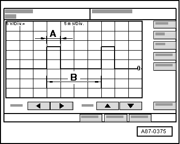
| This display appears on the oscilloscope screen if the following conditions have been satisfied. |
| –
| Ignition switched on (positive and earth applied to the high-pressure sender -G65-) |
| –
| Oscilloscope settings: 5 V/div. = (5 V per unit DC voltage) 5 ms/div. (5 milliseconds per unit) |
| –
| Test lead (signal lead) connected to socket -7- on the test box. |
| –
| Test lead (screening) connected to socket -14- on the test box (earth). |

Note | t
| The illustration shows the signal transmitted at a refrigerant circuit pressure of approx. 7 bar absolute, corresponding to a signal ratio of approx. 25 % (level occurring with the compressor not running, at an ambient temperature of 30 °C and with the refrigerant circuit charged). |
|
|
|
