audi Workshop Repair Guides

Audi Workshop Service and Repair Manuals

Control unit identification (in display zone 2, example) > < Performing self-diagnosis
Connecting vehicle diagnostic, testing and information systemVAS 5051 and selecting functions
Connecting vehicle diagnostic, testing and information system -VAS 5051- and selecting functions
Requirements
t  Supply voltage of vehicle electrical system OK
t  Fuses OK → ”Current Flow Diagrams, Electrical Fault-finding and Fitting Locations”
  Note
t  The various functions of the vehicle diagnostic, testing and information system -VAS 5051- are described in the system operating manuals.
t  The design and function of the vehicle diagnostic, testing and information system -VAS 5051- are described in the → No.202. This also contains some examples of the correct application of this system.
t  Self-diagnosis can also be performed with the fault reader -V.A.G 1551- or the vehicle system tester -V.A.G 1552- in “1 rapid data transfer” mode. The various functions are described in the relevant system operating manuals.
   
–  With the ignition off,connect the vehicle diagnostic, testing and information system -VAS 5051-, by the diagnostic cable -VAS 5051/5A-, for example, to the 16-pin diagnostic socket in the vehicle.
–  Switch on the ignition.
Or
–  Start the engine.
  Note
Observe the notes for final control diagnosis on Page → Chapter.
–  Set the operating mode to “Auto” on the operating and display unit for air conditioner/Climatronic -E87-.
  A87-0311
–  Select the “vehicle self-diagnosis” function on the vehicle diagnostic, testing and information system -VAS 5051-.
  A87-0312
–  Select the vehicle system “08 - Electronic climate/heating control”.
  Note
t  The vehicle system selection prompt appears in display zone -1-.
t  “Scrolling” the screen display with the scroll bar -2- allows you to display the vehicle systems (for all vehicle models and equipment levels) which are intended for self-diagnosis but which cannot be displayed on-screen at present.
  A87-0313
–  Wait until “Select diagnostic function” appears in display zone -1- of the vehicle diagnostic, testing and information system -VAS 5051-.
  Note
t  Control unit identification now appears in display zone -2- of the vehicle diagnostic, testing and information system -VAS 5051- → Chapter.
  A87-0314
t  Check the following if “Vehicle system not available” appears in display zone -1- of the vehicle diagnostic, testing and information system -VAS 5051- display:
t  The power supply to the operating and display unit for air conditioner/Climatronic -E87- as per current flow diagram → "Current Flow Diagrams, Electrical Fault-Finding and Fitting Locations"
t  The wiring from the 16-pin diagnostic socket to the operating and display unit for air conditioner/Climatronic -E87-.
  A87-0315
t  Check the following if an additional display zone -2- with the message “Diagnostic bus fault” and references to possible cause of trouble appears on the vehicle diagnostic, testing and information system -VAS 5051- display:
t  The power supply to the 16-pin diagnostic socket using the current flow diagram → ”Current Flow Diagrams, Electrical Fault-Finding and Fitting Locations”
t  The voltage and the status of the battery -A- → Electrical System; Repair group 01
t  The “Diagnostic bus fault” display with references to the possible cause of trouble also appears on the vehicle diagnostic, testing and information system -VAS 5051- if a problem has occurred during self-diagnosis or in the event of interruption of data exchange between the vehicle diagnostic, testing and information system -VAS 5051- and the operating and display unit for air conditioner/Climatronic -E87-.
t  The current screen display can be printed by selecting the “Print” function on the vehicle diagnostic, testing and information system -VAS 5051- display.
t  Possible causes of trouble can be displayed by selecting the “Help” function on the vehicle diagnostic, testing and information system -VAS 5051- display.
t  Pressing the keys shown on the vehicle diagnostic, testing and information system -VAS 5051- display makes it possible to move forwards or backwards in the program (arrow keys) or to switch functions.
  A87-0315
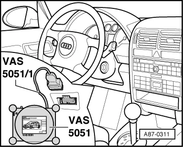
–  The desired function can now be started via the vehicle diagnostic, testing and information system -VAS 5051- display → Chapter (“Available functions” table).
  Note
t  Depending on the version of the operating and display unit for air conditioner/Climatronic -E87- in use, the operating and display unit for air conditioner/Climatronic -E87- switches to “Econ” mode automatically if, following the installation of a new operating and display unit for air conditioner/Climatronic -E87-, no basic setting has been performed or if the pressure measured by the high-pressure sender -G65- is too low or too high (the compressor must not be switched on) → Chapter. (Read measured value block).
t  If the operating and display unit for air conditioner/Climatronic -E87- automatically goes into “Off” mode after the ignition has been switched on and can only be switched to “Def” mode when the ignition is on (whereby other settings are not possible), this indicates that the ignition has, for example, been switched on with a key that has not been enabled for this vehicle or that the control unit in the dash panel is not transmitting a key number via the convenience data bus (depending on the version of the operating and display unit for air conditioner/Climatronic -E87- in use).
  A87-0314

Control unit identification (in display zone 2, example) > < Performing self-diagnosis