
A2
|
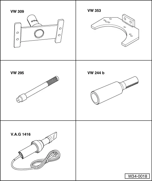
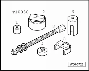
| Special tools and workshop equipment required |
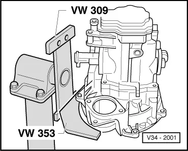
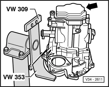
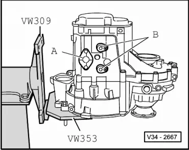
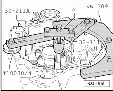
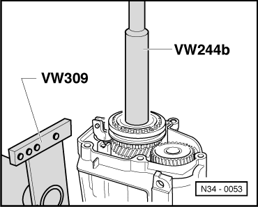
| t | Support plate -VW 309- |
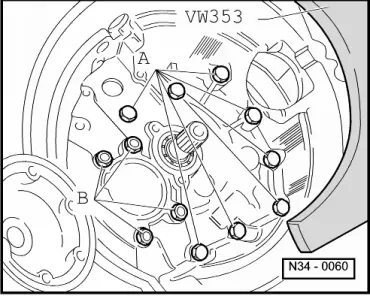
| t | Gearbox support -VW 353- |
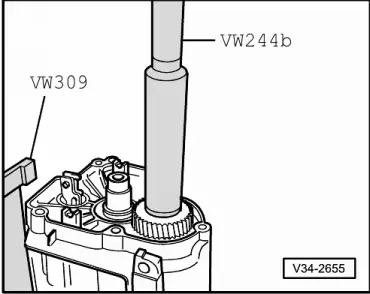
| t | Drift -VW 295- |
| t | Drift sleeve -VW 244 B- |
| t | Hot air blower -V.A.G 1416- |
| t | Sealing grease -G 052 128 A1- |
| t | Sealants -AMV 188 200 03- |
| t | Stud M8 x 100 mm |
| t | Bolt M10 x 20 mm |
|
|
|
|
|
|
|
|
|
|
|
|
|
|
|
|
|
|
 Note
Note
|
|
|
|
|
|
|
|
|
|
|
|
Note
|
|
|
|
|
|
Note
|
|
|
|
Note
|
|
|
|
|
|
Note
|
|
|
|
|
|
|
|
|
|
|
|
|
|
|
|
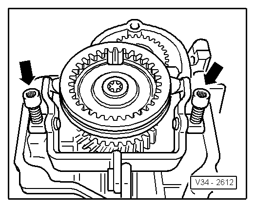
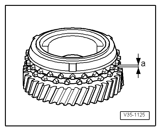
| Gap -a- | Specification | Wear limit |
| 5th gear | 1.1 ... 1.7 mm | 0.5 mm |
|
|
|
|
|
Note
|
|
|
|
|
|
|
|
|
|
|
|
|
|