
A2
| Exploded view - removing and installing selector cables |
 Note
Note| Lubricate all bearings and moving surfaces with polycarbamide grease -G 052 142 A2-. |
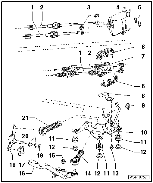
| 1 - | Gate selector cable |
| q | On gate selector lever |
| q | Installation position → Chapter |
| q | Removing and installing → Chapter |
| q | Apply silicone grease -G 000 405 A2- in area of rubber boot/clamping pieces → Anchor |
| 2 - | Gear selector cable |
| q | Press onto gear lever guide |
| q | Installation position → Chapter |
| q | Removing and installing → Chapter |
| q | Apply silicone grease -G 000 405 A2- in area of rubber boot/clamping pieces → Anchor |
| 3 - | Securing clip |
| 4 - | Selector housing |
| 5 - | Retaining clip |
| q | Take care not to damage selector cables when removing. |
| 6 - | Clamping pieces |
| q | Always renew |
| q | Press into rubber boot → Item |
| q | Apply silicone grease -G 000 405 A2- to openings for cables → Anchor |
| 7 - | Rubber boot |
| 8 - | Retaining clip |
| q | For wiring harness |
| q | If fitted |
| 9 - | Bolt |
| q | 20 Nm |
| q | For cable support bracket |
| 10 - | Cable support bracket |
| 11 - | Grommet |
| q | Mounting for cable support bracket on gearbox |
| 12 - | Distance piece |
| 13 - | Nut |
| q | 10 Nm |
| q | Secures retaining clip → Item to cable support bracket |
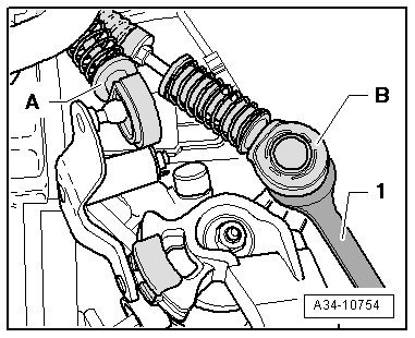
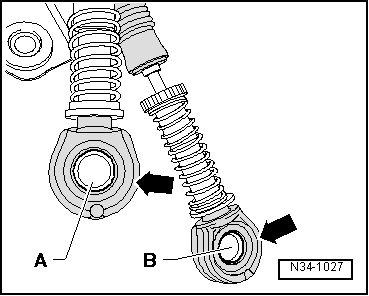
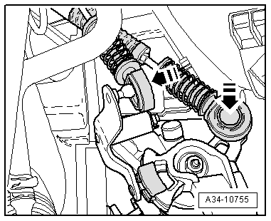
| 14 - | Cable end-piece |
| q | Secures gear selector cable to gearbox selector lever |
| q | Removing → Fig. |
| q | Installing → Fig. |
| q | Must be renewed if removed |
| 15 - | Nut |
| q | 20 Nm |
| q | Self-locking |
| q | Always renew |
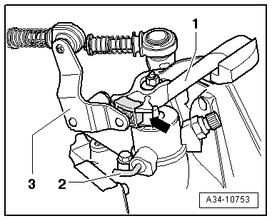
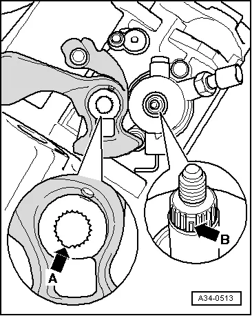
| 16 - | Gearbox selector lever |
| q | With inertia weight |
| q | Install so that gap in splines aligns with selector shaft → Fig. |
| q | After installing, adjust selector mechanism → Chapter |
| q | Installation position → Fig. |
| 17 - | Slide block |
| q | Apply polycarbamide grease -G 052 142 A2- |
| 18 - | Gate relay lever |
| q | Installation position → Fig. |
| 19 - | Securing clip |
| 20 - | Bearing bush |
| 21 - | Cable end-piece |
| q | Secures gate selector cable to gate relay lever |
| q | Removing → Fig. |
| q | Installing → Fig. |
| q | Must be renewed if removed |
|
|
Note
|
|
Note
Note
|
|
|
|