audi Workshop Repair Guides

Audi Workshop Service and Repair Manuals

Removing and installing selector lever pushrod > < Removing and installing selector mechanism
Dismantling and assembling selector mechanism
Special tools and workshop equipment required
   
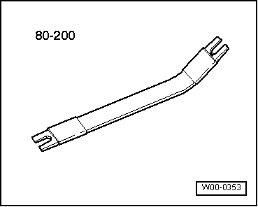
t  Removal lever -80 - 200-
  W00-0353
Dismantling
–  Remove selector mechanism → Chapter.
–  Remove the mount → Chapter.
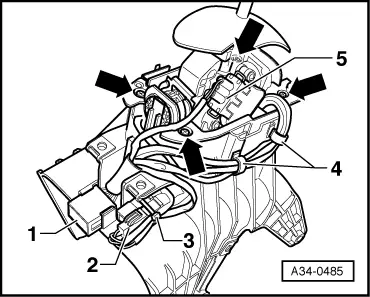
–  Unclip the connector -1-.
–  Unplug electrical connectors -2- and -5-.
–  Sever the cable tie -3- and pull out the cable clips -4-.
–  Remove bolts -arrows- and take selector mechanism out of selector housing.
  A34-0485
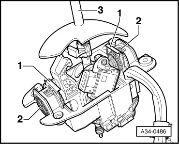
–  Use a screwdriver to press off the lock washers -1-.
–  Press the two selector lever bearing bushes -2- out of the mounting plate.
–  Take out the selector lever -3-.
  A34-0486
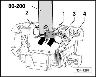
–  Carefully and evenly press off the selector lever detector switch for N -F258--Item 1- with the pressing-off lever -80 - 200-. Whilst doing so, press the retainer tabs -arrows- outwards.
  Note
t  There are 2 pins in the mount which hold the switch in position.
t  It is essential to make sure that these pins do not break off.
–  Press the switches -2, 3, 4- out of the mounting plate mounts.
–  Take the wiring harness with the switches out of the mounting plate.
  N34-1287
Assembling
l  Tightening torque → Chapter
Installation is carried out in reverse sequence; note the following:
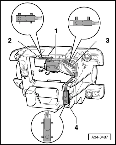
–  Fit the wiring harness with the switches:
1 - Selector lever detector switch for N -F258-
2 - Selector lever detector switch for E -F271-
3 - Selector lever detector switch for stopped -F259-
4 - Selector lever gate detector switch -F257-
  A34-0487
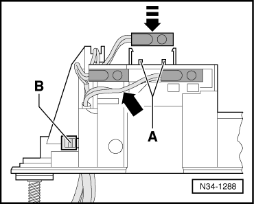
–  Press the selector lever detector switch for N -F258- vertically from above into the mount -top arrow-.
l  Make sure the two lugs -A- do not break off whilst doing so.
–  Press the wire -arrow- into the mounting plate recess and secure with cable ties -B-.
–  Use the current flow diagram to check the wiring and connectors → Current flow diagrams, Electrical fault finding and Fitting locations.
  N34-1288
–  Insert the selector lever -3- in the mounting plate.
–  Slide selector lever bearing bushes -2- from front/rear into mounting plate.
–  Fit lock washers -1- for bearing bushes in mounting plate.
l  The offset ends face inwards.
  A34-0486
–  Insert the selector mechanism in the selector housing and tighten the bolts -arrows-.
–  Clip in the connector -1-, plug in the connector -2- and secure with a cable tie -3-.
–  Plug in the connector -5-.
  A34-0485

Removing and installing selector lever pushrod > < Removing and installing selector mechanism