
A2
| Electric/electronic components in the vehicle |

| 1 - | Relays |
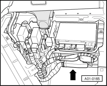
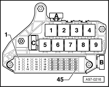
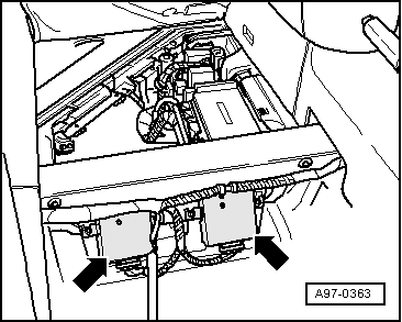
| q | Gearbox hydraulic pump relay -J510- on the 6+6-part relay carrier at the front left of the footwell → Fig. |
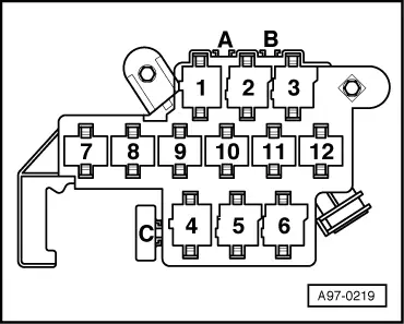
| q | Load shutoff relay -J511- on the 9-part relay carrier, fuse holder in the dash panel on the driver's side → Fig. |
| q | Starter inhibitor and reversing light relay -J226- on the 6+6-part relay carrier at the front left of the footwell → Fig. |
| q | Ignition key removal lock control unit -J557- on the 6+6-part relay carrier at the front left of the footwell → Fig. |
| q | The relays are checked by self-diagnosis |
| q | Removing and installing relays → Electrical system; Rep. Gr.97 |
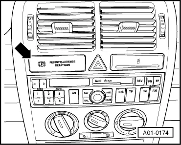
| 2 - | Control unit for handbrake warning lamp -J534- |
| q | Fitting location → Fig. |
| q | Removing and installing → Chapter |
| 3 - | Solenoid valve for ignition key removal lock -N334- |
| q | Fitting location: at the ignition/starter switch |
| q | Can be checked via the electrical test → Chapter |
| q | Removing and installing → Electrical system; Rep. Gr.94 |
| 4 - | Switch for Start/Stop mode -E262- (ECO mode) |
| q | Fitting location: in the centre console |
| q | Can be checked via the electrical test → Chapter |
| 5 - | Selector lever and gear selector mechanism |
| q | With switch for selector lever gate recognition -F257- |
| q | With switch for selector lever N-recognition -F258- |
| q | With switch for selector lever Stop-recognition -F259- |
| q | With lockout switch for diesel engine -F207- |
| q | With selector lever lock solenoid -N110- |
| q | With potentiometer for selector lever, forwards/backwards -G272- |
| q | Fitting location, and removing and installing these components → 5-speed Manual Gearbox 085 DS; Rep. Gr.34 |
| q | All components are checked by self-diagnosis and can be checked with the electrical test → Chapter |
| 6 - | Voltage regulator -J532- and voltage regulator 2 -J570- |
| q | Fitting location → Fig. |
| q | Removing and installing → Chapter |
| 7 - | Door lock with contact switch |
| q | Fitting location: in the door |
| q | The door contact switch signal is transmitted from the central control unit for convenience system -J393- to the electronic manual gearbox control unit -J514- |
| q | Can be checked via reading measured value block → Chapter |
| q | Removing and installing → General Body Assembly, Exterior; Rep. Gr.57 |
| 8 - | Electronic manual gearbox control unit -J514- |
| q | Fitting location → Fig. |
| q | Removing and installing → Chapter |
| q | Checked via self-diagnosis → Chapter „Connecting vehicle diagnostic, testing and information system -VAS 5051 A- and selecting functions“ |
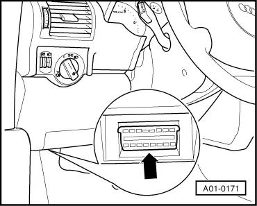
| 9 - | Diagnostic connector |
| q | Fitting location → Fig. |
| 10 - | Gearbox |
| q | Electrical/electronic components on gearbox → Chapter |
| 11 - | Hydraulic control unit |
| q | Electric/electronic components on hydraulic control unit → Chapter |
| 12 - | Brake pressure switch -F270- |
| q | Fitting location: on right, next to hydraulic control unit |
| q | Can be checked electrically → Chapter and via reading measured value block → Chapter |
|
|
|
|
|
|
|
|
|
|