audi Workshop Repair Guides

Audi Workshop Service and Repair Manuals

List of selectable functions > < Safety precautions
Connecting vehicle diagnostic, testing and information systemVAS 5051 A and selecting functions
Connecting vehicle diagnostic, testing and information system -VAS 5051 A- and selecting functions
Requirements:
l  Selector lever in position “N” and handbrake applied.
l  Supply voltage of vehicle electrical system OK
l  Fuses OK → Current flow diagrams, Electrical fault finding and Fitting locations
l  Earth connections for gearbox OK
–  Check earth connections for corrosion and damaged connections and repair, if necessary → Current flow diagrams, Electrical fault finding and Fitting locations.
  Note
Earth attachment point is located underneath the starter.
Procedure
   
–  Connect the vehicle diagnostic, testing and information system -VAS 5051 A- with diagnostic cable -VAS 5051 A/1- to the diagnostic connector with the ignition switched off.
  WARNING
Observe the safety precautions → Chapter.
  Note
If a fault message appears in the display → Operating instructions of vehicle diagnostic, testing and information systemVAS 5051 A.
–  Switch on ignition.
or
–  Start engine.
  A87-0311
Display on -VAS 5051 A-:
–  Touch “Vehicle self-diagnosis” key.
  A87-0312
Display on -VAS 5051 A-:
  Note
Touching the diagnostic function “00 - Interrogate fault memory - entire system” in list -1- implements the automatic test sequence, i.e. fault memory interrogation takes place for all vehicle systems with self-diagnosis capability.
–  From list -1- select vehicle system “02 - Gearbox electronics”.
–  Wait until next readout appears.
  A01-0120
Display on -VAS 5051 A-:
2 - Gearbox control unit identification.
  A87-0314
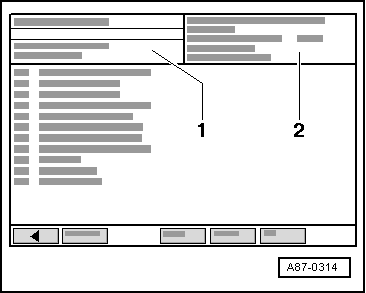
Gearbox control unit identification (example)
02 - Gearbox electronicsVehicle system
6N0927735..Part No.; For correct allocation refer to → Parts catalogue
DS085 Gearbox A..Direct manual gearbox 085
Code 0Control unit code, ignore display

If readout “Vehicle system not available” appears in display zone -1-:
–  Check:
t  The voltage supply to the diagnostic connector → Current flow diagrams, Electrical fault finding and Fitting locations.
t  Wiring connections from diagnostic connector to electronic manual gearbox control unit -J514- → Current flow diagrams, Electrical fault finding and Fitting locations.
   

List of selectable functions > < Safety precautions