
A2
| Removing engine |

| Special tools and workshop equipment required |
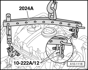
| t | Shackle -10-222 A/12- |
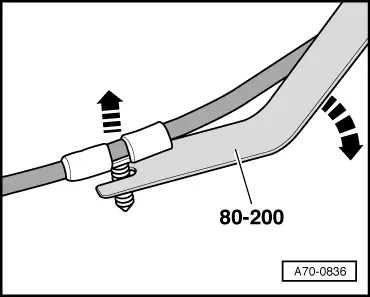
| t | Removal lever -80-200- |
| t | Lifting tackle -2024 A- |
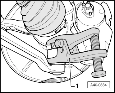
| t | Ball joint puller -3287 A- |
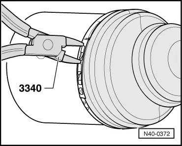
| t | Pliers -3340- |
| t | Hose clip pliers -V.A.G 1921- |

| t | Workshop hoist -VAS 6100- |
| t | Drip tray for workshop hoist -VAS 6208- |
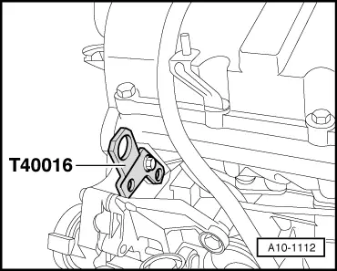
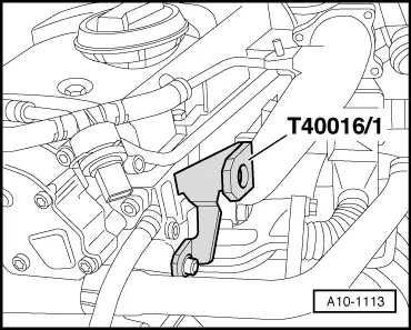
| t | Transportation shackle -T40016- with -T40016/1- |
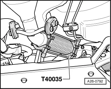
| t | Setting tool -T40035- |
 Note
Note
Note |
 Caution
|
|
 WARNING
Note |
|
|
|
|
|
|
|
Note |
|
|
|
Note
|
|
Note
|
|
|
|
|
|
|
|
|
|
Note
|
|
|
|
|
|
|
|
|
|
|
|
|
|
|
|
|
|
Note
|
|
|
|
Note
|
|
Note
|
|
|
|
|
|
|
|
|
|
|
|
Note
|
|
|
|
|
|
|
|
|
|
|
|
|
|
|
|
|
|
|
|
|
|
|
|
Note
|
|
|
|
Note
|
|
Note
|
|
|
|
|
|
|
|
Note
|
|
Note
|
|
Note
Note |
|
|
|
Note
|
|
|
|
|
|
Note
Note |
|
|
|
Note
|
|
|
|