
A2
| Diagram of coolant hose connections |
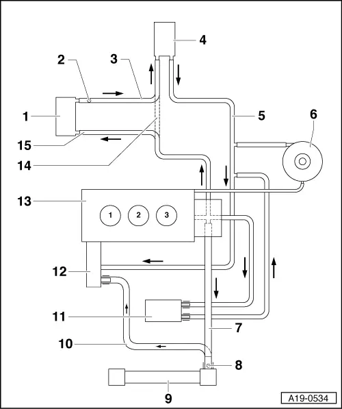
| 1 - | Exhaust gas recirculation cooler or auxiliary heater |
| q | Exhaust gas recirculation cooler is only fitted on engines with code letters ATL |
| q | Fitting of auxiliary heater depends on equipment level |
| 2 - | Bleeder screw |
| 3 - | Coolant pipe |
| 4 - | Heat exchanger |
| q | If renewed, refill system with fresh coolant |
| 5 - | Coolant pipe |
| 6 - | Coolant expansion tank |
| q | With filler cap |
| q | Checking pressure relief valve in filler cap → Anchor |
| 7 - | Coolant hose |
| 8 - | Bleeder screw |
| 9 - | Radiator |
| q | Removing and installing → Chapter |
| q | If renewed, refill system with fresh coolant |
| 10 - | Coolant hose |
| 11 - | Oil cooler |
| q | If renewed, refill system with fresh coolant |
| q | Removing and installing → Chapter „Removing and installing oil filter bracket“ |
| 12 - | Coolant pump/thermostat |
| q | Removing and installing coolant pump → Chapter |
| q | Checking thermostat → Chapter |
| q | Removing and installing thermostat → Chapter |
| 13 - | Cylinder head/cylinder block |
| q | If renewed, refill system with fresh coolant |
| 14 - | Coolant pipe |
| q | Going to heat exchanger on vehicles without exhaust gas recirculation cooler or auxiliary heater |
| 15 - | Coolant pipe |
| q | To exhaust gas recirculation cooler or auxiliary heater |