
A2
|
|
|
|
|
 Note
Note |
|
|
|
 WARNING
|
|
Note
|
|
|
|
|
|
|
|
Note
|
|
|
|
|
|
|
|
|
|
|
|
|
|
Note
|
|
 Caution
|
|
|
|
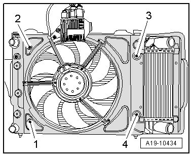
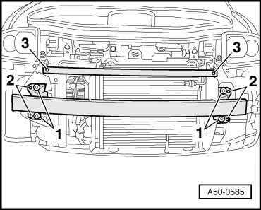
| Component | Nm |
| Charge air cooler to radiator | 6 |
| Radiator to radiator cowl | 6 |
| Condenser to radiator cowl | 6 |
| Air ducts to radiator cowl | 1.5 |