
A2
| Removing and installing toothed belt |
| Special tools and workshop equipment required |
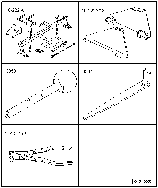
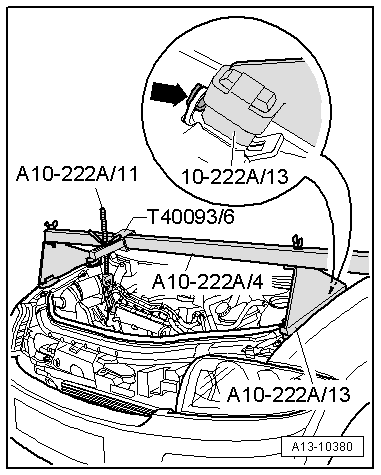
| t | Support bracket -10 - 222 A- |
| t | Adapter -10 - 222 A /13- |
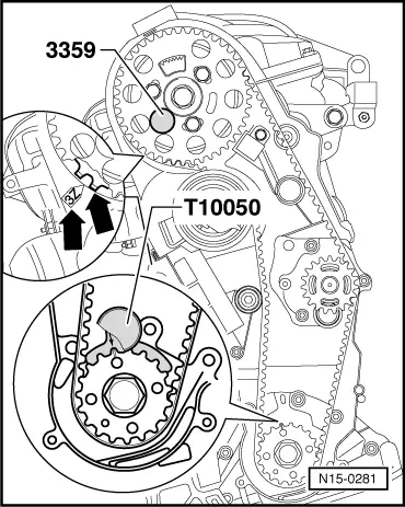
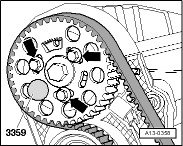
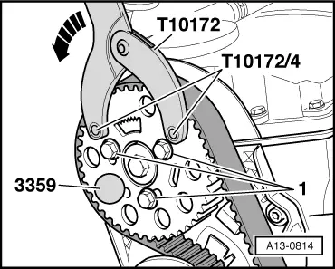
| t | Diesel injection pump locking pin -3359- |
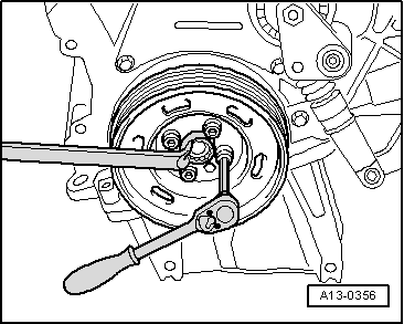
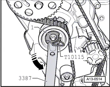
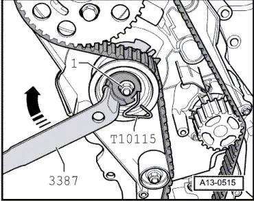
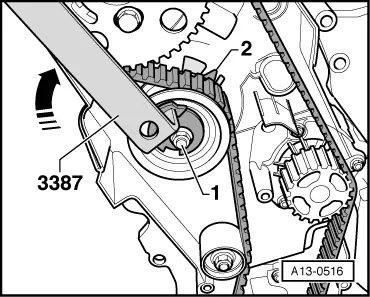
| t | Pin wrench -3387- |
| t | Hose clip pliers -V.A.G 1921- |
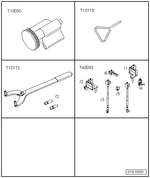
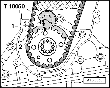
| t | Crankshaft stop -T10050- |
| t | Locking pin -T10115- |
| t | Counterhold tool -T10172- with pin -T10172/4- |
| t | Adapter -T40093/6- from engine support bracket (supplementary set) -T40093- |
| t | Locking fluid → Parts catalogue |
|
|
|
|
 Note
Note
|
|
|
|
|
|
|
|
|
|
Note
|
|
|
|
|
|
|
|
|
|
Note
|
|
|
|
 Caution
|
|
|
|
Note
|
|
Note
|
|
Note
Note
|
|
|
|
Note
|
|
|
|
|
|
Note
Note
|
|
|
|
Note
|
|
|
|
Note
|
|
Note
|
|
| Component | Nm | ||||
| Camshaft sprocket to hub | 25 | ||||
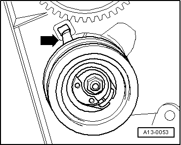
| Tensioning roller for toothed belt to cylinder head | 20 + 45° 1) | ||||
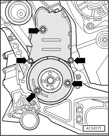
| Toothed belt cover (bottom) to cylinder block | 10 2) | ||||
| Toothed belt cover (centre) to cylinder block | 10 2) | ||||
| Engine support to cylinder block | 45 | ||||
| Tensioner for poly V-belt to bracket for ancillaries | 22 | ||||
| Engine cover panel to bracket | 5.5 | ||||
| |||||